Flow meter nominal capacity, Flow meter coefficient – Fill-Rite TS AA Mechanical Precision Meter User Manual
Page 4
1 . 4
TS Series, Anodized Aluminum - Specifications for V●● assemblies
Materials
Case : Anodized aluminum
Rotors : PPS with carbon bearings,
(oval gears)
Teflon
TM
bearings optional.
Posts : HC303SS
Seals : Viton
TM
standard,
Teflon
TM
optional.
Connections
Bolted companion flanges with NPT or BSP port;
Optional: Anodized
aluminum
welding
flanges
Carbon
steel
welding
flanges
Carbon
steel
150#
RF
ANSI
adaptors
Pressure Rating at 100°F (38°C) with 3:1 Safety Factor
Meter/Strainer
: 150 PSI/100°F = 10.3 BAR/40°C
Air Elim/Valves: 150 PSI/100°F = 10.3 BAR/40°C
Temperature Rating
V
assy
: -40°F to +180°F = -40°C to +80°C
Use HT or HV rotors if temp. can exceed 120°F = 50°F
Meter Performance
When field calibrated on actual liquid of service
Linearity
Over 5:1 turn-down from max. capacity : ±0.175%
Over 10:1 turn-down from max. capacity : ±0.30%
Over 30:1 turn-down from max. capacity : ±0.5%
Repeatability
0.05% or better under constant conditions
Nominal Capacity
With LV rotors on 1-300 cP viscosity:
With HV rotors on 5-1000 cP viscosity:
GPM LPM m
3
/h
TS10A 40 150 9
TS15A 60
230
14
TS20A** 150
570
34
TS30A** 200
760
45
** = On low viscosity lubricating liquids, intermittent
use to 125% of capacity is permitted.
Viscosity
With LV rotors 100% capacity to 1,500 SSU/300 cP.
With HV rotors 100% capacity to 5,000 SSU/1,000 cP.
With HV rotors, the flow meter may be used to
1,500,000 SSU/350,000 cP at reduced flow rates (see
meter viscosity/coefficient table in next column).
Opt. Pulsers on mechanical register
10:1 pulser 100:1 pulser
1/10
gallon
register 10
PPG
100
PPG
Whole gallon register 1 PPG 10 PPG
1/10
liter
register
10
ppl
100
ppl
Whole liter register 1 ppl 10 ppl
Dekaliter
register 0.1
ppl
1
ppl
●
●
●
●
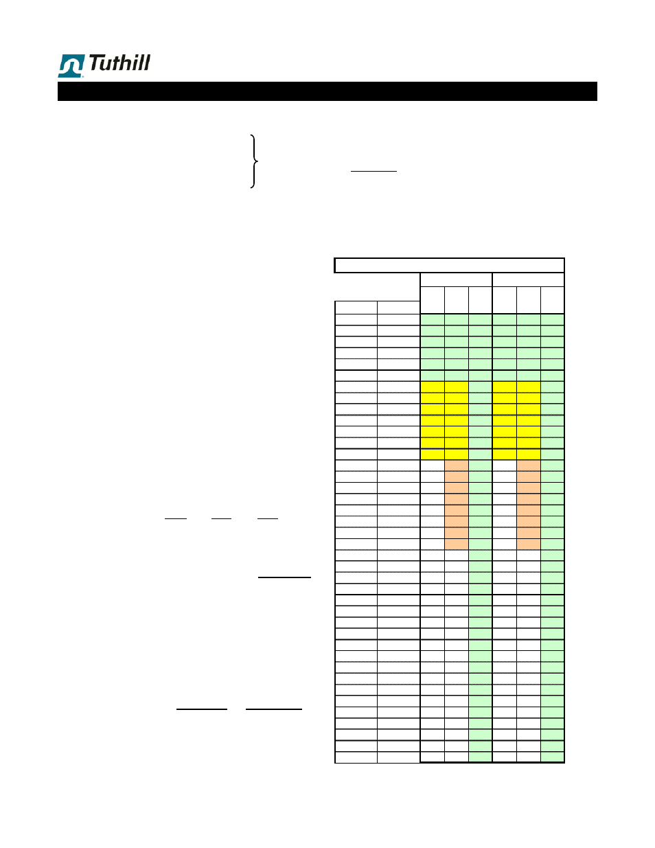
Rotor
B
L
I
C
M
J
Code
SSU
cSt
LV
HT
HV
LV
HT
HV
TYPE
32
1 1.00 1.00 1.00 1.00 1.00 1.00
60
10 1.00 1.00 1.00 1.00 1.00 1.00
240
50 1.00 1.00 1.00 1.00 1.00 1.00
465
100 1.00 1.00 1.00 1.00 1.00 1.00
925
200 1.00 1.00 1.00 0.90 0.90 1.00
1,415
300 0.86 0.86 1.00 0.73 0.73 0.98
1,890
400 0.77 0.77 1.00 0.62 0.62 0.96
2,360
500 0.71 0.71 1.00 0.57 0.57 0.94
2,830
600 0.66 0.66 1.00 0.53 0.53 0.92
3,300
700 0.63 0.63 1.00 0.50 0.50 0.90
3,775
800 0.60 0.60 1.00 0.48 0.48 0.85
4,250
900 0.56 0.56 1.00 0.45 0.45 0.80
4,720
1,000 0.54 0.54 1.00 0.43 0.43 0.75
9,440
2,000
0.35 0.77
0.28 0.65
14,150
3,000
0.28 0.65
0.22 0.55
18,875
4,000
0.24 0.58
0.19 0.46
23,600
5,000
0.19 0.53
0.15 0.42
28,325
6,000
0.16 0.49
0.13 0.39
33,050
7,000
0.14 0.47
0.11 0.37
37,750
8,000
0.12 0.44
0.09 0.35
42,475
9,000
0.10 0.42
0.08 0.34
47,200
10,000
0.41
0.32
94,400
20,000
0.30
0.24
141,600
30,000
0.24
0.19
188,800
40,000
0.20
0.16
236,000
50,000
0.18
0.14
283,200
60,000
0.17
0.13
330,400
70,000
0.14
0.11
377,600
80,000
0.13
0.10
424,800
90,000
0.12
0.10
472,000
100,000
0.11
0.09
944,000
200,000
0.08
0.06
1,416,000
300,000
0.07
0.05
1,888,000
400,000
0.06
0.05
2,360,000
500,000
0.06
0.04
2,832,000
600,000
0.06
0.04
3,304,000
700,000
0.05
0.04
3,776,000
800,000
0.05
0.04
4,248,000
900,000
0.05
0.04
4,720,000 1,000,000
0.05
0.04
Intermittent service = < 6 hours/day,
and deliveries not to exceed 15-20 minutes.
On higher viscosity liquids,
model nominal capacity is
reduced
as per tables below .
Liquid Viscosity
Flow Meter Coefficient
Carbon brgs. Teflon brgs.
Normal operating range is w ith 10:1 turn-dow n from model
nominal capacity.
Flow Meter
nominal capacity
:
On low viscosity liquids, best performance (linearity/service life)
is betw een 50% and 85% of model nominal capacity.
On diesel fuel, TS20A & TS30A models w ith mechanical
register only may be operated to 125% of nominal capacity in
intermittent service
(this does NOT apply to models with
preset and/or printer).
See cover for
rotor & seal
materials in
this meter.