Safety instructions, Servicing the flow meter – Fill-Rite TS AA Mechanical Precision Meter User Manual
Page 13
Always coat bolt threads with an anti-seize, or an appropri-
ate lubricant to prevent thread damage, and to assure prop-
er torque values are applied when reassembling.
If flow meter threads are damaged, repair using inserts.
Servicing the Mechanical Drive Components
Flow meter wear depends upon several variable factors
(flow rate vs model capacity, lubricity of the liquid, total vol-
ume being metered annually and maintenance of mechani-
cal register, preset and/or printer), so it is impossible to pre-
dict the expected life for each component.
There are 8 parts or components, which will require inspec-
tion and/or replacement at some point. In the order they are
likely to occur, these are:
Regular Maintenance (1-3 years)
A. Face Gear (11E) & Packing Gland Pinion (11D)
B. Packing Gland O-ring (11B)
Longer Term Wearing Components (2-5 years)
C. Calibrator Drive Shaft Assembly (21)
D. Gear Plate, internal (4)
Very Long Term Wearing Components (3-10 years)
E. Packing Gland (11)
F. Oval Gears (2), or inspection of measuring chamber
Longest Term Wearing Components (5-20 years)
G. Post Plate assembly (3)
H. Calibrator Assembly (19)
Of these, only A, C & H can be performed without taking the
pressure off the system and draining the flow meter. The
remaining all require opening of flow meter interior.
The first step is to remove the dust cover (
see pages 1.8-9
)
from the RAD (14 = Right Angle Drive adaptor).
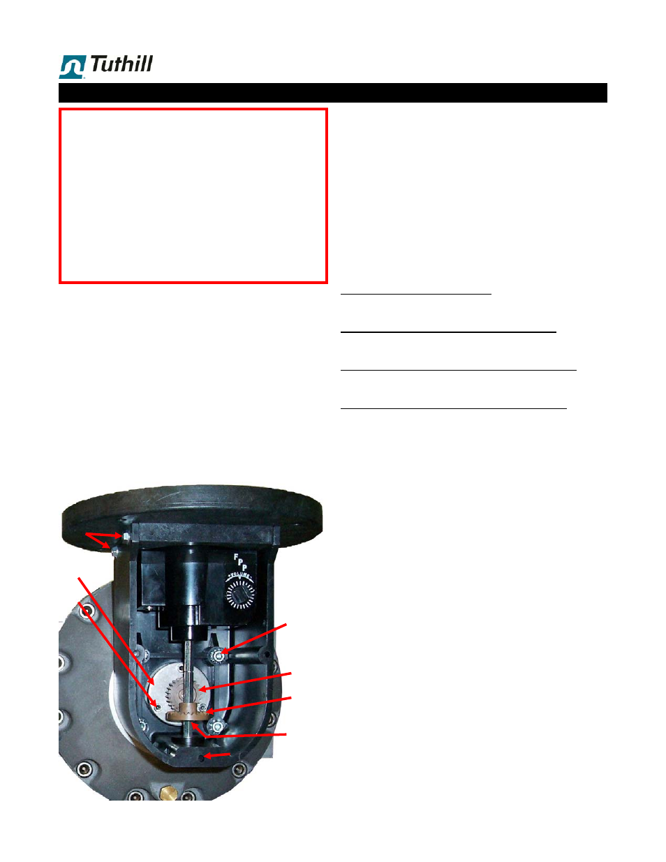
A. Face Gear (11E) & Packing Gland Pinion (11D)
C. Calibrator Drive Shaft Assembly (21)
Always replace Face Gear & Packing Gland Pinion together.
They can be ordered under a single P/No. (see page …).
Remove E-ring (21F) from the drive shaft assembly (21)
with a screwdriver or small pliers.
Loosen the set screw (18) with a 3/32” Allen wrench, to
release the calibrator drive shaft bushing (21B).
Slide the calibrator drive shaft bushing (21B) out of the
bottom of the RAD (14), and pull the calibrator drive shaft
assembly out of the RAD.
Replace Face Gear (11E) on the calibrator drive shaft
assembly.
Remove E-ring (11C) from the packing gland (11) with a
screwdriver or small pliers, and replace the Packing
Gland Pinion (11D).
Reassemble in reverse order.
Servicing the Flow Meter
Installation, Maintenance & Service must be performed
by personnel:
A. Qualified to work on this type of equipment.
B. Familiar with all applicable local codes and ordi-
nances covering the type of service, where the flow
meter is used (gasoline, LPG, etc.).
Avoid pipe strain and stress when making flow meter re-
pairs. The weight of piping and the flow meter should be
supported independently. This means that the meter can be
serviced without affecting piping alignment.
Avoid prying or exerting heavy pressure on precision parts,
as this could affect the performance of the flow meter.
Assure that all machined parts are free of burrs and nicks.
Stone all machined surfaces if necessary to remove burrs.
14a
14b
26
19
18
11C/D
11E
21F
1 . 13
12
13
! SAFETY INSTRUCTIONS !
REMOVE ALL INTERNAL PRESSURE
BEFORE OPENING THE FLOW METER.
DRAIN & RINSE THE FLOW METER
BEFORE SERVICING.
IF IT IS NECESSARY TO TRANSPORT OR
SHIP THE FLOW METER TO A DIFFERENT
LOCATION FOR SERVICE, IT
MUST
BE
RINSED
3 TIMES
WITH A NEUTRAL FLUID
PRIOR TO TRANSPORTATION/SHIPMENT.
27/28