Servicing the flow meter – Fill-Rite TS AA Mechanical Precision Meter User Manual
Page 14
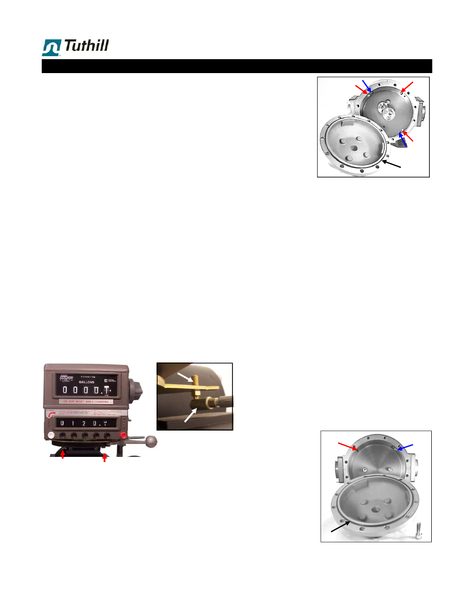
You now have access
to the Gear Plate as-
sembly (4). If rebuild-
ing with repair kit, no
further disassembly is
required.
If replacing the oval
gears, inspecting the
measuring chamber or
replacing the complete
gear plate:
Remove 4 screws (6) from the gear plate. The gear plate
can now be pulled off dowel pins (5),
using a 5/16-8 x 1”
jack bolt if necessary
.
The gear plate assembly can now be rebuilt or replaced
as required.
Prior to removing the rotors (oval gears), use a soft pencil
to make an alignment mark where the gears engage.
This will make re-assembly easier.
The oval gears can now be inspected or replaced as re-
quired. When placing the oval gears back on the posts,
make sure that they are aligned and spin freely on the
posts. If they are not aligned correctly, they will disen-
gage.
The measuring chamber can now be inspected. Remove
any deposits using a fine emery cloth or wire brush. Be
careful to remove any particulate material, which can
cause the meter to jam.
A minor scratch in chamber surface can be carefully
smoothed out, but be careful not to cause scoring or to
change the dimensions. If the measuring chamber shows
signs of scoring from rotors rubbing, it should be re-
placed.
Re-assemble in reverse order.
G. Post Plate assembly (3)
First relieve system pressure and drain the flow meter.
Remove the cover
bolts (10) from the
rear cover (9), now
remove the rear cov-
er from the flow me-
ter and inspect the
cover O-ring (7) for
flaws. Teflon fitted
meters: Always re-
place seals when
opening the flow me-
ter.
Servicing the Flow Meter
B. Packing Gland O-ring (11B)
E. Packing Gland Assembly (11)
First relieve system pressure and drain the flow meter.
Then follow instructions for above for removal of calibrator
drive shaft assembly. Remove E-ring (11C) from the pack-
ing gland assembly, and pull off the pinion (11D).
Remove three screws (13) from the packing gland retain-
er (12). Remove the retainer
Packing Gland O-ring and/or Packing Gland assembly
can now be replaced.
When replacing the Packing Gland, the drive dog must be
aligned with the slot in the gear on the gear plate.
Reassemble in reverse order.
D. Gear Plate, Internal (4)
F. Oval Gears (2), or inspection of measuring chamber
The wearing parts in the Gear Plate assembly are the reduc-
tion gears. On a longer time scale, the bushing in the gear
plate will wear out. The gear plate assembly can be rebuilt
or replaced in one of 3 ways, with d.3 being what is most
commonly required:
d.1 Complete gear plate assembly
d.2 Gear plate/bushing assembly only, re-using gears.
d.3 Repair kit, with reduction gears & fasteners.
First relieve system pressure and drain the flow meter.
Also, detach the mechanical register stack, to take the
weight off of flow meter front cover.
If the mechanical register stack includes a preset counter,
detach the linkage from the trip ring (see top of next column)
prior to taking the register stack off.
Remove dust cover & calibrator drive shaft as explained
above.
Remove 4 screws/washers (27/28) holding the RAD to
the front cover (8).
Remove the cover bolts (10) from the front cover (8), now
remove the front cover from the flow meter and inspect
the cover O-ring (7) for flaws. Teflon fitted meters: Al-
ways replace seals when opening the flow meter.
Valve linkage connects to
preset trip ring at the rear.
Slide the sleeve towards
the shaft to release the
mounting stud.
Register stack attaches to the RAD
with 4 screws, 2 front and 2 rear.
STUD
SLEEVE
6
4
5
8
7
1 . 14
7
5
6
9
3
10