Flow meter calibration – Fill-Rite TS AA Mechanical Precision Meter User Manual
Page 12
When prover/master meter reading is
less than
flow
meter
register reading,
add percentage
calculated
by turning the calibrator in the
+ volume direction
.
When prover/master meter reading is
more than
flow
meter register reading
,
subtract percentage
calcu-
lated by turning the calibrator in the
- volume direction
.
After correcting calibrator setting, circulate product
through the flow meter for a few minutes. Then perform
at least 3 more tests, to confirm flow meter accuracy &
repeatability.
If the flow meter does not repeat, it will likely require a
new set of rotors (oval gears).
Before ordering new gears, inspect the measuring
chamber for scratches or wear. If the measuring
chamber is scratched or scored beyond what can be
smoothed with emery paper, flow meter case should
be replaced.
Finally:
Re-seal the flow meter.
Enter date and % correction on the permanent flow
meter record.
As long as degree of change is moderate, the flow meter is
in good condition.
If there is a sudden significant jump in correction required,
the rotors are likely about worn out. Rotor replacement
should be considered now, rather than letting further wear
cause rotors to start rubbing on flow meter housing.
1 . 12
Flow Meter Calibration
Procedures & Methods
Flow meters used in systems where the flow rate can fluctu-
ate, should be tested at minimum, intermediate & maximum
flow rates. In non-W&M service, a flow meter always oper-
ating at a steady flow rate, can be tested at that flow only.
All tests should be repeated 3 times to confirm repeatability.
All tests should be of at least 60 second duration, to mini-
mize the effect of flow meter error during start-up and shut-
down.
After calibrating a known volume (X) into an accurate
prover, through a master meter, or against a certified
scale with adequate resolution, compare with register
reading (Y) and calculate correction:
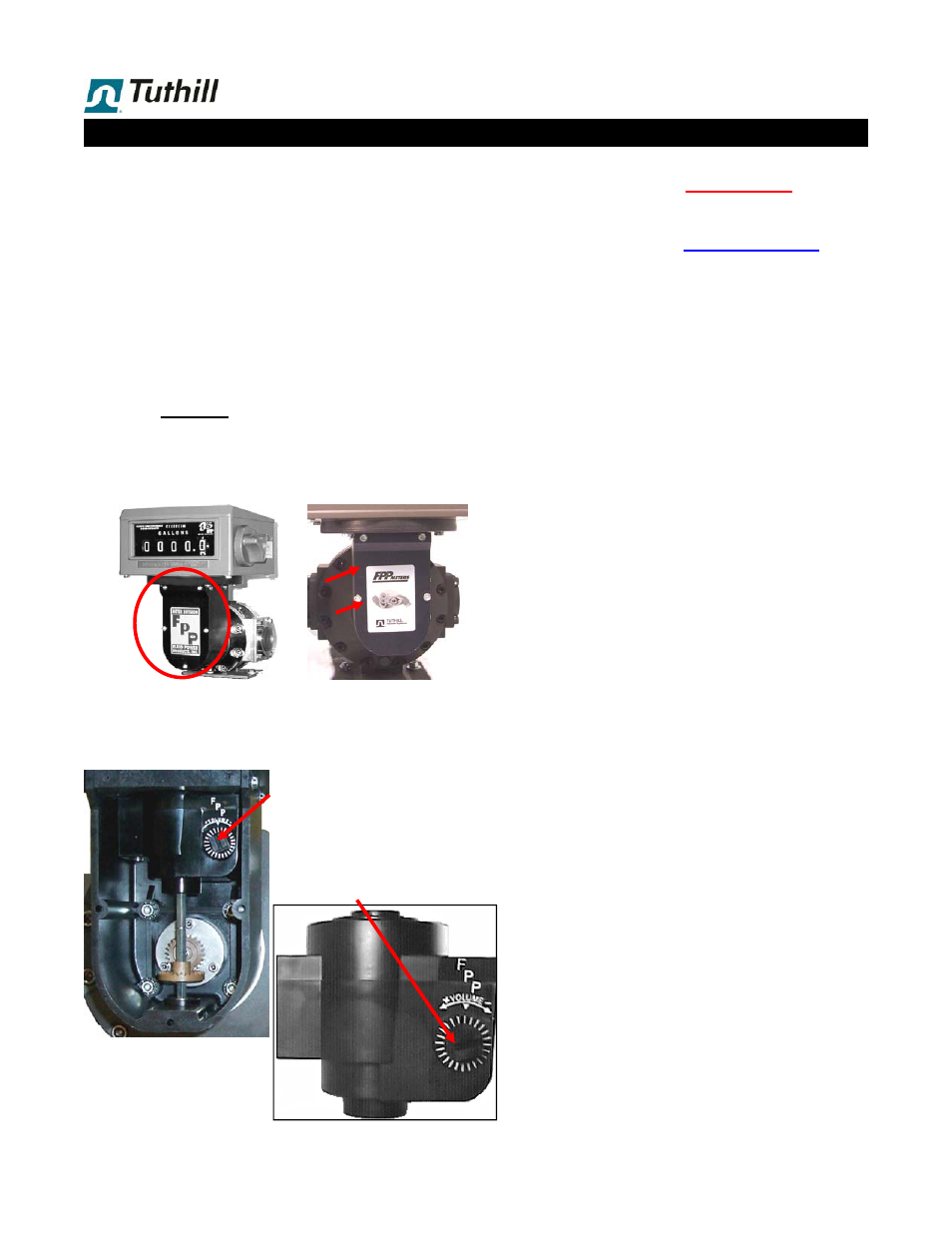
When re-calibration has established that a correction is
required, remove the dust cover (15) from the RAD (14 =
right angle drive adaptor), by detaching screws (16 & 17).
This provides access to the calibrator assembly (19),
which has a dial on the front, and is marked with direc-
tions for + and - Volume. Each graduation of this dial
represents approx. 0.06% change
The dial has a
slot for a
screw driver
in the center, so
the setting can be changed.
As you turn the center, you will
hear two ‘clicks’ for each grad-
uation mark. Each ‘click’ rep-
resents approximately 0.03%
change in the setting.
Do NOT change setting,
unless re-calibration of the
flow meter has established
the need for correction.
19
X - Y
X
x 100
= % correction
17
15
16
14
19