Calibration, mechanical flow meters – Fill-Rite TS AA Mechanical Precision Meter User Manual
Page 11
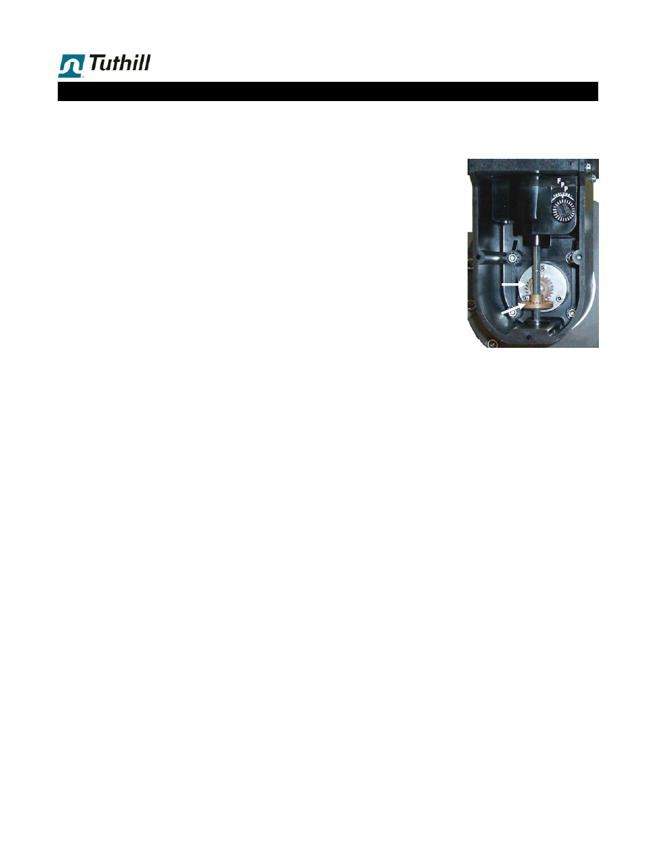
Mechanical TS Series meters have a mechanical drive train
directly from the rotors (oval gears) to the register. To con-
vert rotor movement to volume reading on the register, this
drive train includes 3 calibration components:
Packing gland pinion (11D)
can have 12 or 24 teeth,
while the face gear (11E)
always has 24 teeth, re-
sulting in a 1:1 or 2:1 ratio.
The appropriate ratio de-
pends upon flow meter
model size & specific unit
of calibration selected for
the register.
Mechanical calibrator (19).
This component makes
minute adjustments to final
calibration to compensate
for individual flow meter
characteristics, viscosity of
fluid being metered, and
flow meter wear factor.
A ratio gear plate installed below the mechanical register.
Gearing on this gear plate is specific to flow meter model
& unit of calibration selected. Optimum ratio is between
0.5000 & 5.0000 for best service life.
The mechanical register is common to all flow meter mod-
els, so it is possible to move registers from one flow me-
ter to another.
Do NOT move the ratio gear plate from
one flow meter to another
.
.
Frequency of Re-Calibration
In installations subject to local Weights&Measures regula-
tions, frequency of recalibration must conform to such
regulations.
If local authorities issue regulations for non-W&M flow
meters, such regulations must be observed.
If user is ISO9000 certified, user ISO standards will indi-
cate frequency of re-calibration for instrumentation.
Those standards should be observed.
When no regulations or standards apply, our recommenda-
tions are:
A. Calibrate immediately after installation.
B. Re-calibrate after 15-30 days.
C. Re-calibrate after 180 days and again after 360 days.
After the run-in calibration (B) and follow-up calibrations (C),
it is possible to evaluate degree of change under normal
operating conditions. Based on values found, and total vol-
ume being metered under normal operating conditions, de-
cide whether a 6, 12 or possibly 24 month schedule should
be adopted.
1 . 11
Calibration, Mechanical Flow Meters
W&M Certifications:
TS10A
US
TS15A
US
&
Canada
TS20A US, Canada, EU & Australia
TS30A US, Canada, EU & Australia
Certifications are liquid specific. Please refer to national
certificates for liquid categories covered.
Flow Meter Calibration at the Factory
All TS Series meters are accuracy tested prior to shipment.
Data from accuracy testing is not supplied with flow meters,
since results achieved on our test fluid do not apply to actual
liquid of operation, unless the two liquids have identical vis-
cosity characteristics.
When calibrated on a liquid with 1 cP viscosity, if the flow
meter is not field recalibrated on actual liquid of service, we
expect that the flow meter will be:
Under by 1-2% on a liquid with 0.5 cP viscosity.
Over by 0.35% to 0.6% on a liquid with 10 cP viscosity.
Over by 0.7% to 1.2% on a liquid with 100 cP viscosity.
The accuracy curve will not shift significantly at higher vis-
cosities, even if the actual operating liquid has viscosities up
to 500,000 cP.
Accuracy curves of individual flow meters vary slightly.
Such minor variations are corrected in the mechanical cali-
brator. In our calibration procedure, the meter calibrator is
set for zero error, when operating at 95-100% of capacity on
1 cSt viscosity fluid.
Flow Meter Calibration in The Field
Since we cannot test on actual fluid of operation, it is the
responsibility of the buyer to field calibrate:
In place of service
On actual operating liquid.
This will minimize errors arising from:
A. Operation at a different flow rate.
B. Operation on a fluid with different viscosity
It is recommended that written records be maintained on all
flow meters. These records should include:
Supplier and Service Department phone number.
Date of installation.
Details of maintenance performed.
Date & result of each re-calibration, with % change made
on flow meter calibrator assy.
11D
11E
19