Changing direction of flow – Fill-Rite TS AA Mechanical Precision Meter User Manual
Page 10
Now loosen the set screw (18) with a 3/32” Allen wrench,
to release the calibrator drive shaft bushing (21B).
Slide the calibrator drive shaft bushing (21B) out of the
bottom of the RAD (14).
Pull the calibrator drive shaft assembly out of the RAD.
Remove the face gear (11E), and turn it 180º, so that the
gear teeth are facing in the opposite direction from the
original installation.
Re-assemble the parts in reverse order.
Make sure that the calibrator drive shaft bushing flange
(21B), is tight against the RAD (14).
Tighten the hex nut (21C)
Re-install the E-ring (21F) in the appropriate grove (
in
the above example, the E-ring now goes into groove above
the pinion
).
Inspect to make sure that there is slight backlash be-
tween the pinion gear (11D) and the face gear (11E).
They must engage without binding or slipping.
1 . 10
Changing Direction of Flow
TS Series flow meters can operate in either direction.
Standard assembly, when facing the flow meter, has the
flow going Left-to-Right, unless specified differently at time
of the order. A label with the word INLET is placed on the
inlet flange, as assembled at the factory.
When the meter is first installed, check that the register is
turning correctly when you start the flow. If it is not (or it is
attempting to run backwards), check position of the face
gear (11E) on the calibrator drive shaft (21A), and if neces-
sary correct the position of the face gear versus the packing
gland pinion (11D) as explained below.
Left-to-Right flow = Face gear below packing gland pinion
Right-to-Left flow = Face gear above packing gland pinion
The direction of flow can be changed in the field. This re-
quires the following steps:
Any accessories (strainer and/or preset valve) attached to
the flow meter must be moved to the opposite side.
Strainer inlet is standard from the front. When mov-
ing the strainer to Right-to-Left position, switch the
inlet flange and strainer basket cover. If rear inlet is
preferred, leave flange & basket cover as is, when
moving the strainer.
Standard outlet on Preset Valve or Air Check Valve
is towards the front. When moving the valve to Right-
to-Left position:
Air Check Valve: Rotate the valve 180º, then in-
stall tubing connecting air eliminator to the valve.
Preset Valve: Rotate the valve 180º. Disassem-
ble the linkage, and re-assemble mirror image to
original assy.
Reverse the position of the face gear (11E) on the cali-
brator drive shaft (21A).
First remove screws (16 & 17) to detach the dust cover
(15) from the RAD (14 = Right Angle Drive) adaptor.
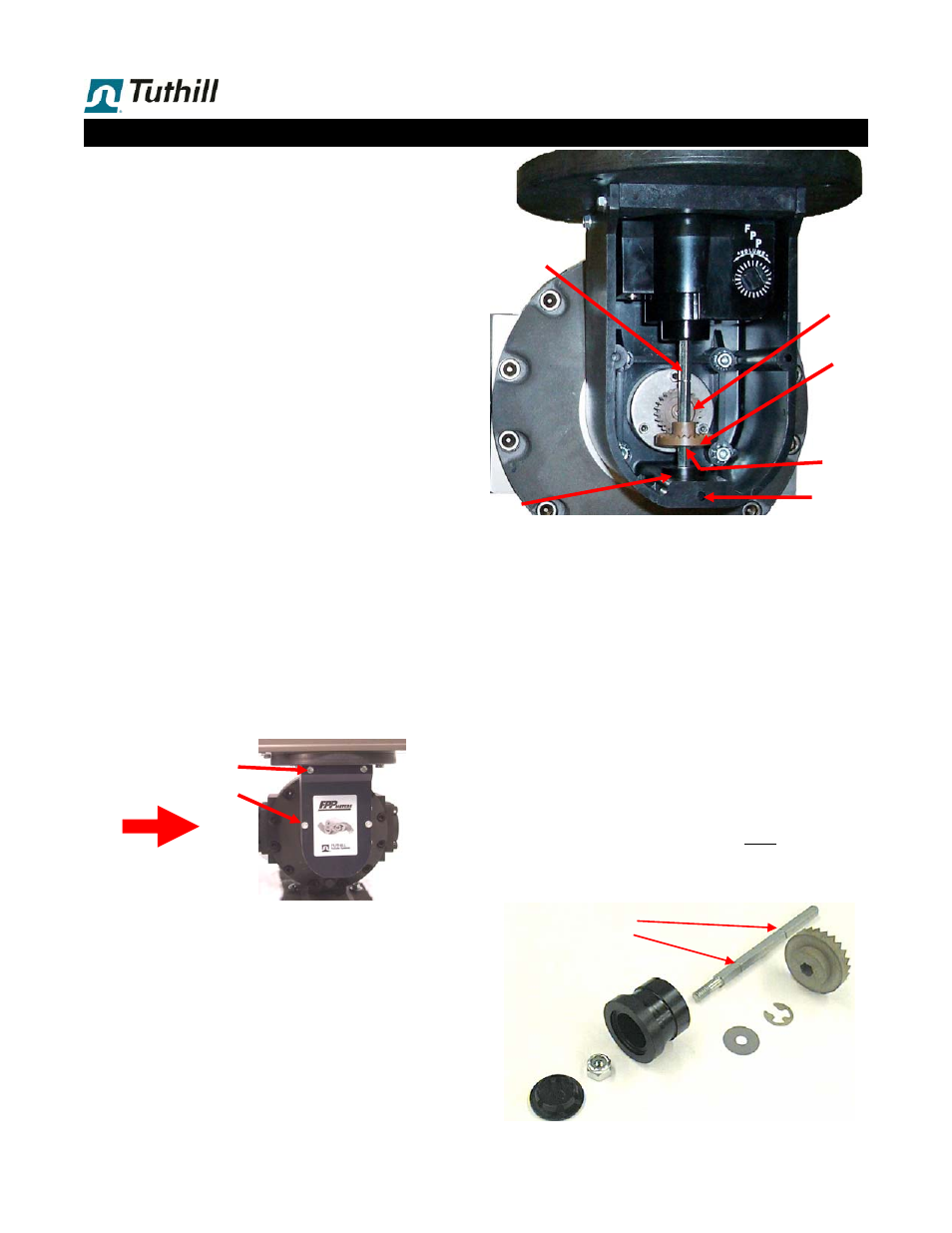
Now refer to photo in next column.
Notice position of the face gear (11E) on the calibrator
drive shaft (21A) in relation to the packing gland pinion
(11D).
Remove E-ring (21F) with a screwdriver or small pliers.
As shown, the E-ring is installed below the face gear,
where it is not visible in the photo.
11E
11D
21A
18
INLET
19
14
INLET
21B
16
17
15
14
21E
21B
21C
21D
21E
21F
11E
21A = Drive shaft with 2 grooves:
Upper
Lower