Serial no. terminology, Index – Fill-Rite TS AA Mechanical Precision Meter User Manual
Page 2
INDEX
Section . Page
FPP Meters and Principle of Operation . . . . . . . . . . . . . . . . . . . . . . . . . . . . . . . . . . . . . . 1 . 3
Material Specifications, Capacity & derating on high viscosity liquids . . . . . . . . . . . . 1 . 4
Part No. and Assy No. break-down . . . . . . . . . . . . . . . . . . . . . . . . . . . . . . . . . . . . . . . . . . 1 . 6-7
Safety Instructions . . . . . . . . . . . . . . . . . . . . . . . . . . . . . . . . . . . . . . . . . . . . . . . . . . . . . . . 1 . 8
Installation, Start-Up & Operation Procedures . . . . . . . . . . . . . . . . . . . . . . . . . . . . . . . . 1 . 8-9
Reversing Direction of Flow . . . . . . . . . . . . . . . . . . . . . . . . . . . . . . . . . . . . . . . . . . . . . . . 1 . 10
Flow meter Calibration & Re-Calibration . . . . . . . . . . . . . . . . . . . . . . . . . . . . . . . . . . . . . 1 . 11-12
Servicing the Flow Meter . . . . . . . . . . . . . . . . . . . . . . . . . . . . . . . . . . . . . . . . . . . . . . . . . . 1 . 13-15
Troubleshooting the Flow Meter . . . . . . . . . . . . . . . . . . . . . . . . . . . . . . . . . . . . . . . . . . . . 1 . 17
Flange kits . . . . . . . . . . . . . . . . . . . . . . . . . . . . . . . . . . . . . . . . . . . . . . . . . . . . . . . . . . . . . 1 . 16
Parts List, models TS10A, TS15A, TS20A & TS30A . . . . . . . . . . . . . . . . . . . . . . . . . . . . 1 . 18
Exploded View . . . . . . . . . . . . . . . . . . . . . . . . . . . . . . . . . . . . . . . . . . . . . . . . . . . . . . . . . . 1 . 19
Torque & Tools chart . . . . . . . . . . . . . . . . . . . . . . . . . . . . . . . . . . . . . . . . . . . . . . . . . . . . . 1 . 20
Warranty . . . . . . . . . . . . . . . . . . . . . . . . . . . . . . . . . . . . . . . . . . . . . . . . . . . . . . . . . . . . . . . 1 . 20
Strainers . . . . . . . . . . . . . . . . . . . . . . . . . . . . . . . . . . . . . . . . . . . . . . . . . . . . . . . . . . . . . . . 2 . 1
Parts List, standard Strainer (2” & 3”) . . . . . . . . . . . . . . . . . . . . . . . . . . . . . 2 . 2
Parts
List,
High
Capacity
Strainer
(2”
&
3”)
. . . . . . . . . . . . . . . . . . . . . . . . . 2 . 3
Air Eliminator, incl. Parts List . . . . . . . . . . . . . . . . . . . . . . . . . . . . . . . . . . . . . . . . . . . . . . 2 . 4-5
Backpressure Valve, incl. Parts List . . . . . . . . . . . . . . . . . . . . . . . . . . . . . . . . . . . . . . . . 2 . 6
Air Check Valve, incl. Parts List . . . . . . . . . . . . . . . . . . . . . . . . . . . . . . . . . . . . . . . . . . . . 2 . 7
Name of Distributor who supplied this flow meter: ________________________________
Phone number for Distributor Service Department: ________________________________
1 . 2
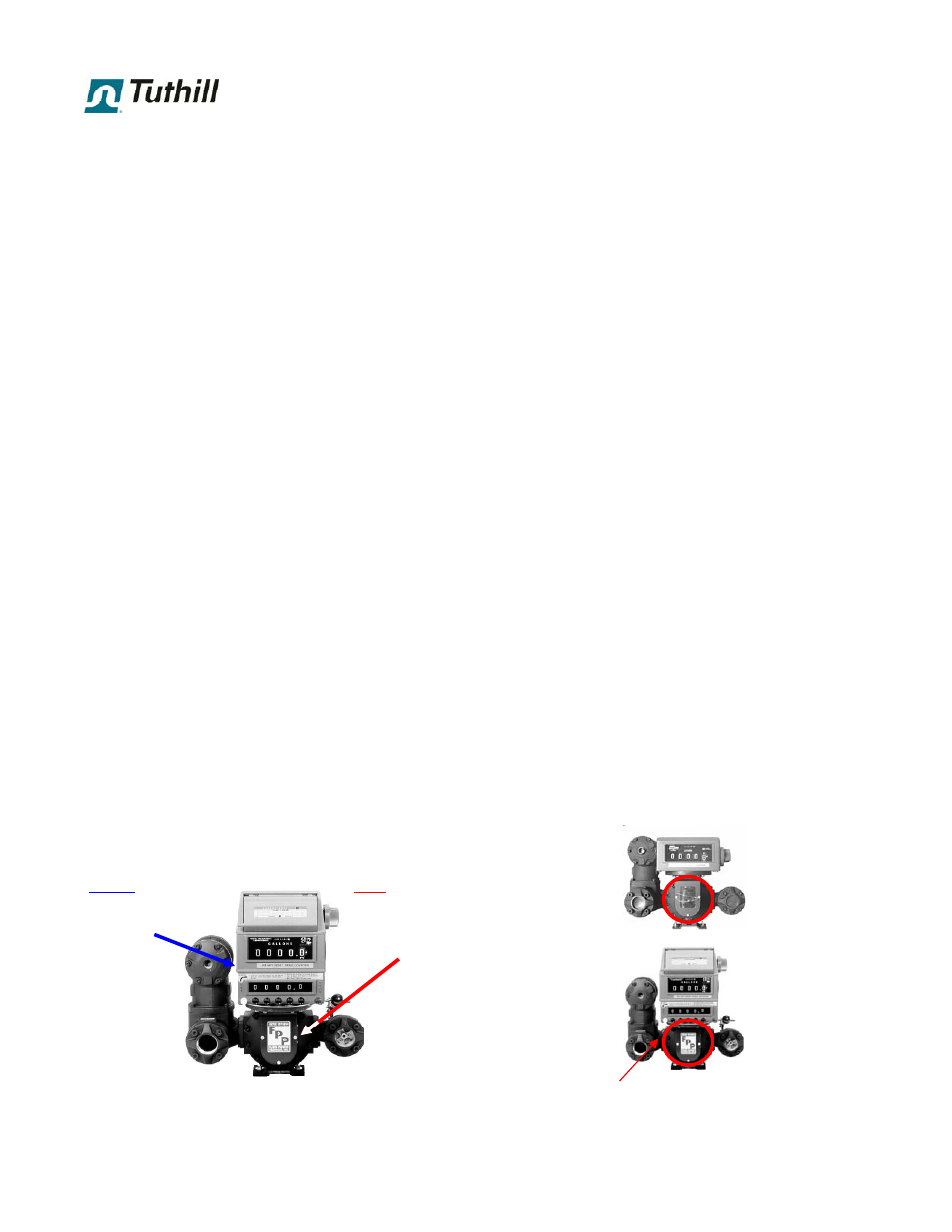
Meter S/No. is on the
spec plate, which is
located on the side of
the Right Angle Drive
register adaptor.
Register S/No. is on the
register spec plate, which
is on the side of
the register.
PRINTER
REGISTER
PRESET COUNTER
PRESET VALVE
AIR ELIMINATOR
STRAINER
BACKPRESSURE
VALVE
(not visible)
Serial No. Terminology
This flow meter is the subject of a continuing improvement program. The possible components in this
flow meter
are:
To ensure correct supply of replacement parts, every parts inquiry
must include the Serial No. from the original flow meter assembly.
FLOW
METER
REGISTER
AIR CHECK
VALVE
AIR ELIMINATOR
STRAINER