Ts series - exploded view, mechanical (v●● assy.) – Fill-Rite TS AA Mechanical Precision Meter User Manual
Page 19
1 . 19
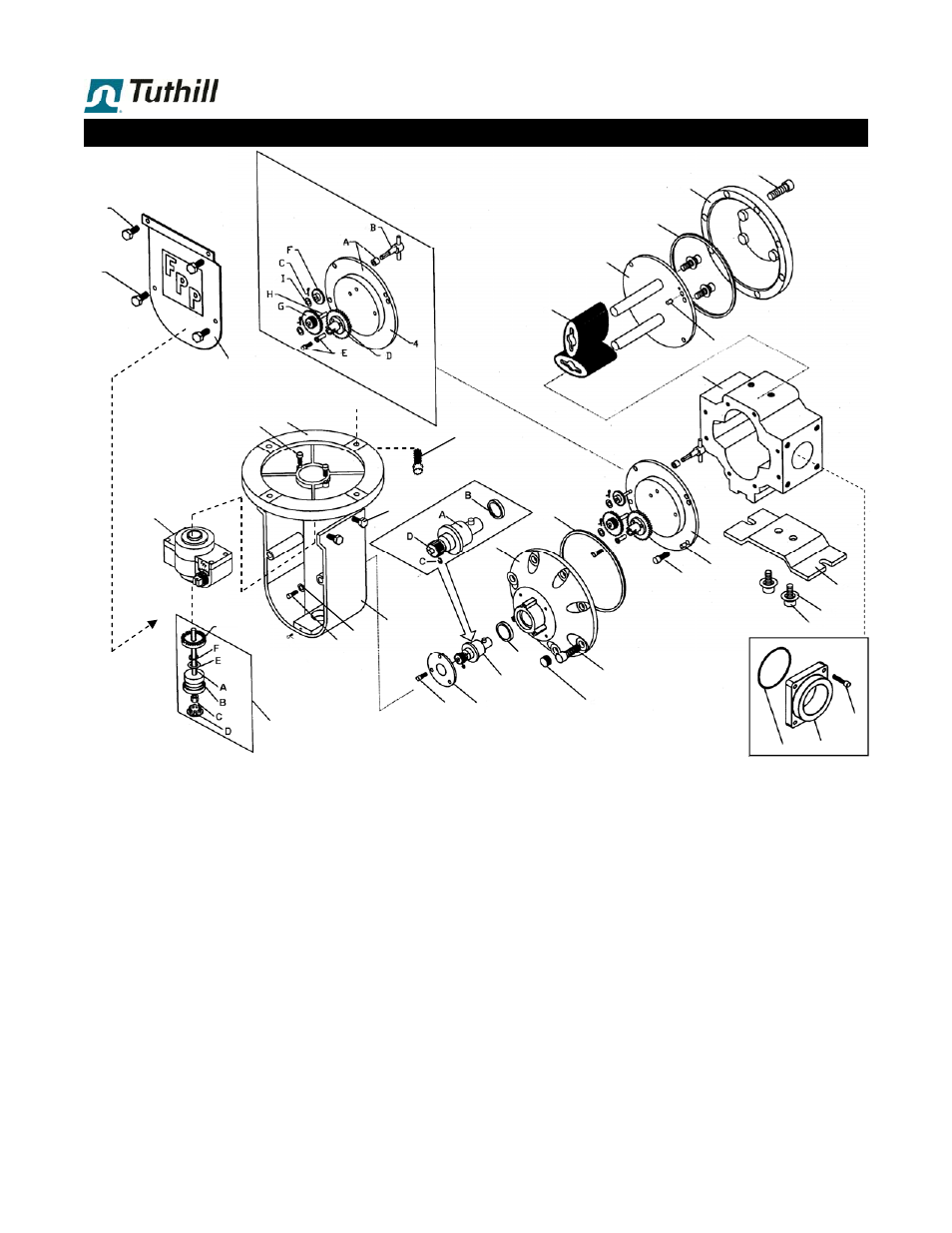
TS Series - Exploded View, Mechanical (V●● Assy.)
16
14a
12
1
2
3
8
15
17
18
11
20
19
13
4
5
5
6
7
9
10
7
14b
27
21
11E
24
23
25
29
22
26
28
A
B
C
#4 = Gear Plate assembly (internal)
Can be replaced complete, or as two sub-assemblies (the
individual parts are not sold separately, as they must be
replaced as a set):
Gear plate with bushing (4A)
Rebuild kit (items 4B-4I)
#29 = Companion Flanges
Companion flange assemblies (A+B+C) vary, depending on
whether the flange attaches to:
Flow meter body
Inlet strainer
Preset valve or air check valve on flow meter outlet.
A complete list of companion flange assemblies, seals and
screws is found on page 1.16
#11 = Packing Gland
The packing gland ratio (D = 12 or 24 tooth pinion) de-
pends upon flow meter model, and unit of calibration select-
ed on the mechanical register. A list of packing gland ratios
can be found in FPP Technical Manual (see list of ratio
gear plates).
Pinion/Face Gear (11D/E) can be replaced separately:
GS2001 2:1, metal/PPS
GS2002 1:1, PPS/PPS (standard)
GS2003 1:1, metal/PPS (for tank truck service)
The packing gland is replaced as a kit under the P/No.
shown in the parts list, which includes both GS2001 &
GS2002.
#21 = Calibrator Drive Shaft assy.
This assembly is replaced as a kit containing all components
(A-F). Except for the E-ring (F) and face gear (11E), parts
are not sold separately.
3A
10
11B
30