Powerware 6000 User Manual
Page 63
UPS Operation
55
Powerware
®
9 Prestige Series User’s Guide (4500/6000 VA)
S
Rev H
www.powerware.com
4. Remove the cord connections to the back of the PPU.
5. Switch the circuit breaker on all battery cabinets to the
OFF (O) position.
6. Disconnect the battery connector on the PPU rear panel.
7. Remove the PPU.
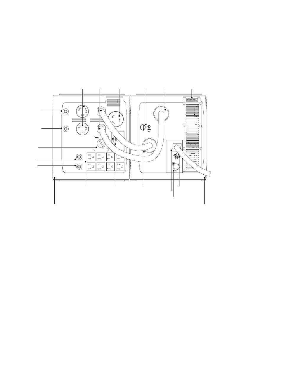
5-15R
Circuit
Protectors
Power
Cords
To PPU
PPU
PPDM
Output
Receptacle
Voltage Selector
Switch
REPO
Receptacle
Battery
Connector
L5-30R, L6-20R,
L6-30R, or L14-30R
Receptacles
(Model Dependent)
Circuit
Protectors for
Locking
Receptacles
(Model
Dependent)
Utility Input
Receptacle
(Cord
Provided)
PPDM
Input
Breaker
Bypass
Switch
5-15R
Receptacles
Power
Processor
Input Plug
Power
Processor
Input
Breaker
Serial Port
Figure 24. UPS with PPDM Rear Panel Connections
This manual is related to the following products: