Powerware 6000 User Manual
Page 40
Installation
32
Powerware
®
9 Prestige Series User’s Guide (4500/6000 VA)
S
Rev H
www.powerware.com
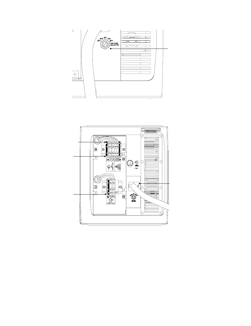
Voltage
Selector
Switch
Figure 9. Voltage Selector Switch
5. Remove the four screws on the PPU rear panel with a Phillips
screwdriver and remove the PPU back panel cover.
Input Cable
Connections
(TB1-1 to TB1-3)
REPO
Connections
(TB1-4 to TB1-6)
Output Cable
Connections
(TB2)
Battery
Connector
Figure 10. Hardwired PPU with Rear Panel Cover Removed
This manual is related to the following products: