Thermostat installation – Honeywell SERIES COMMUNICATING TB7600 User Manual
Page 4
TB7600 SERIES COMMUNICATING RTU/HEAT PUMP THERMOSTATS
62-2016—01
4
Thermostat Installation
Wiring Identification and Screw Terminal Arrangement
Table 1.
Terminal identification
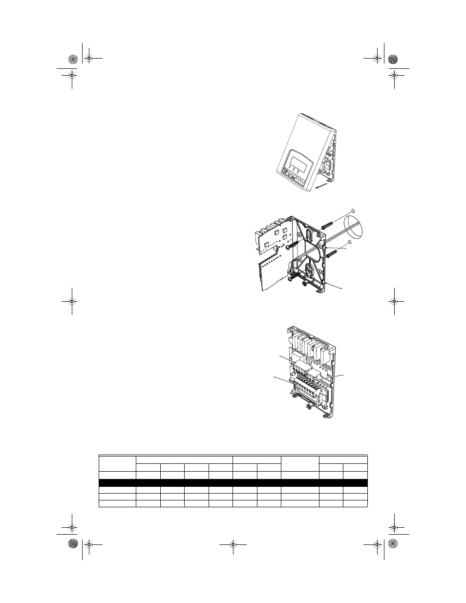
1. Open up by pulling on the bottom side of thermostat.
(Fig. 2)
2. Remove wiring terminals.
3. Open the thermostat PCB to the left by pressing the PCB
retaining tabs. (Fig. 3).
4. Pull cables 6 inches out of the wall.
5. Thread cable through the central hole of the base.
6. Align the base and mark the location of the two mounting
holes on the wall. Install proper side of base up.
7. Install anchors in the wall.
8. Insert screws through the mounting holes on each side of
the base and mount base on wall. (Fig. 3).
9. Gently swing back the circuit board back to the base and
push on it until the tabs lock it in place.
10. Strip each wire 1/4 inch.
11. Wire the terminals. See Table 1 for terminal descriptions and
wiring diagram.
12. Gently push back excess cable into hole.
13. Install wiring terminals in correct location (Fig. 4).
14. Reinstall the cover (top first).
15. Install security screw on the bottom, center of the thermostat
cover.
Model Number
Multistage
1H/1C
Model Number
Heat Pump
TB7656B TB7605B TB7652B TB7600B TB7652A TB7600A
TB7652H TB7600H
Programmable
Yes
No
Yes
No
Yes
No
Programmable
Yes
No
Top left terminal block
Y2
X
X
X
X
Y2
X
X
Y1
X
X
X
X
X
X
Y1
X
X
G
X
X
X
X
X
X
G
X
X
°C
°F
M21300
Fig. 2. Remove cover of thermostat
PCB
RETAINING
TABS
PCB
RETAINING
TABS
M21301
Fig. 3. Location of PCB retaining tabs and
mounting screws
TOP LEFT
5 POLE
CONNECTOR
BOTTOM
8 POLE
CONNECTOR
TOP RIGHT
3 POLE
CONNECTOR
M21302
Fig. 4. Terminal blocks
62-2016.fm Page 4 Thursday, April 14, 2011 1:40 PM