HP 354556-002 User Manual
Page 74
74
HP BladeSystem p-Class Enclosure Installation Guide
IMPORTANT: All power configuration switches in the same zone must
be set to the same position. The system issues alerts and the
management link connector LEDs on the power management modules
flash when these switches are set improperly.
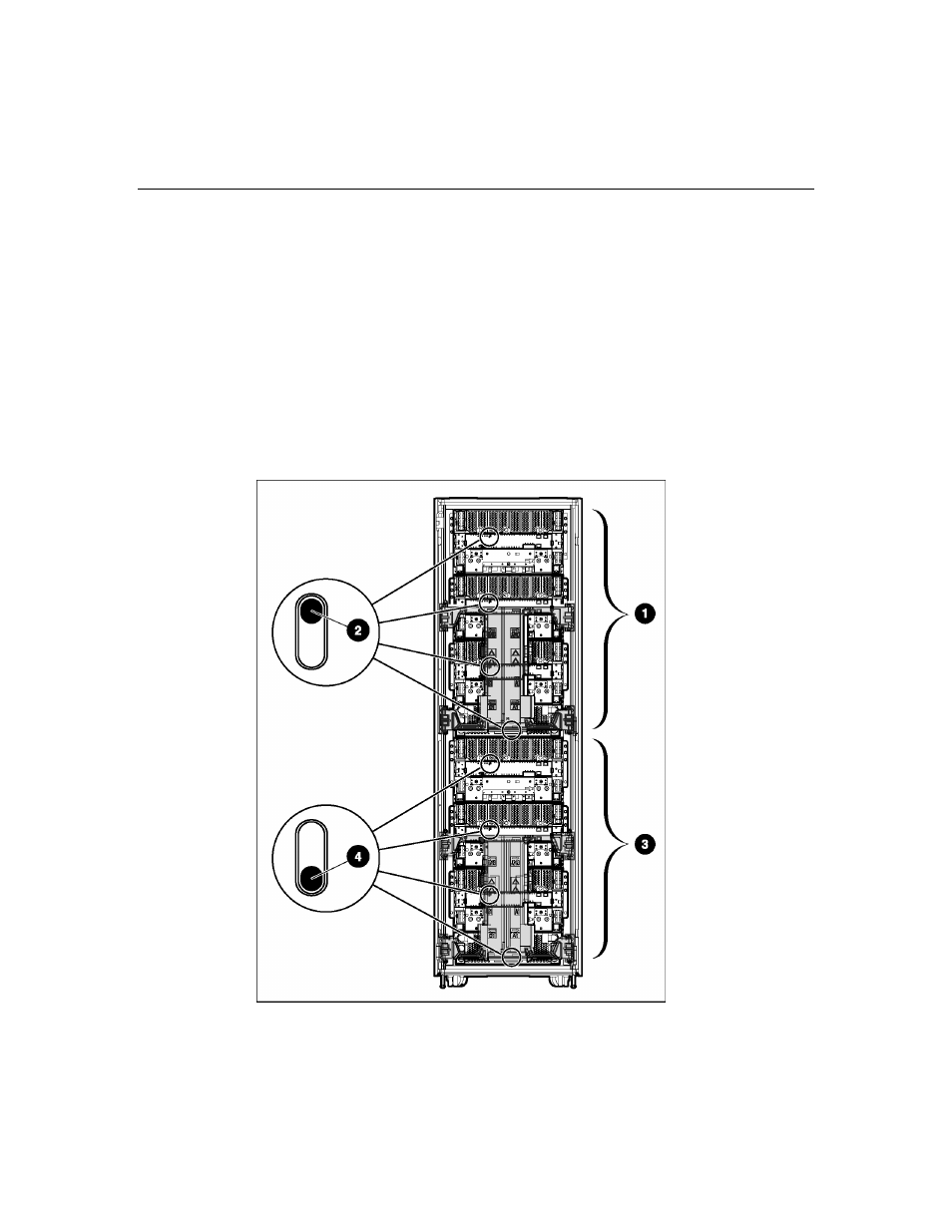
To set the switches for multiple power zones, use the following example and
figure.
Example: A full-rack 42U solution with two pairs of mini bus bars requires two
power zones. To distinguish the two power zones, set all the power configuration
switches on management modules in the upper zone (zone 2) to the up position;
the power configuration switches on the management modules in the lower zone
(zone 1) remain in the down (default) position.
See also other documents in the category HP Computers:
- UX B6941-90001 (548 pages)
- A3661B (95 pages)
- C100/110 (252 pages)
- L1702 (45 pages)
- 576X-B (1 page)
- rx5670 (13 pages)
- ProLiant PC2-6400 (38 pages)
- PC (120 pages)
- S3240 (2 pages)
- LC 2000R (194 pages)
- GS80 (41 pages)
- COMPAQ DX2710 MT (107 pages)
- TOUCHSMART 9100 (62 pages)
- BC1500 (13 pages)
- Proliant DL580 (48 pages)
- Proliant DL580 (53 pages)
- DX2200 (31 pages)
- ProLiant Server Blade BL460c (31 pages)
- P6000 (105 pages)
- d530 Series (2 pages)
- dc5700 (216 pages)
- RX7620-16 (43 pages)
- ProLiant ML370 G5 (46 pages)
- PROLIANT ML350 G6 (54 pages)
- BL35P (22 pages)
- COMPAQ DC5750 (214 pages)
- Agent-Desktop-Laptop Computer (23 pages)
- DL380 G7 (126 pages)
- xw8600 (73 pages)
- Pavilion A6140 (2 pages)
- Z800 (55 pages)
- 8080 ELITE BUSINESS (284 pages)
- VECTRA VL800 (72 pages)
- Vectra XE320 (82 pages)
- Vectra XE320 (32 pages)
- AA-RTDRB-TE (146 pages)
- BL465C (66 pages)
- DM4 (113 pages)
- PROLIANT 580554-001 (87 pages)
- ProLiant ML330 (34 pages)
- ProLiant ML330 (44 pages)
- PROLIANT BL465C G7 (30 pages)
- LH 3r (23 pages)
- Compaq dc7900 (3 pages)
- T5000 (41 pages)