HP 354556-002 User Manual
Page 73
LEDs, buttons, and switches
73
The server blade management modules and power management modules have a
two-position switch that identifies the use of single or multiple power zones in
the rack environment. In installations configured with HP BladeSystem p-Class
3U Power Supply Enclosures, you must set these switches at the time of
installation for the system to recognize multiple power zones and rack topology
properly.
The zone 1 switch setting is the default position. It is used for scalable bus bar,
single mini bus bar, and power bus box solutions. The zone 2 switch setting is
only used for a secondary power zone when you configure a full-rack 42U
solution with two pairs of mini bus bars.
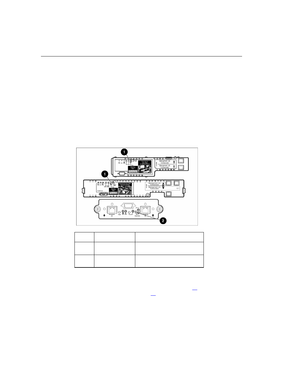
Use the following figure and table to identify switch locations and functions.
Item Description
Function
1
Reset switch
Reinitializes management
functions
2 UID
switch
Toggles UID LED between on
and off
After the initial power-up, use the LEDs to verify correct switch settings. Refer
to the "Server blade management module LEDs (on page
)" and "Power
management module LEDs (on page
)" sections in this guide.