HP FIPS 140-2 User Manual
Page 9
Security Policy, version 1.0
January 31, 2008
HP StorageWorks Secure Key Manager
Page 9 of 26
© 2008 Hewlett-Packard Company
This document may be freely reproduced in its original entirety.
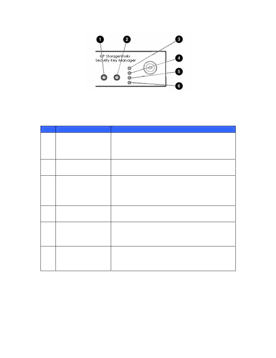
Figure 3 – Front Panel LEDs
Descriptions of the LEDs are given in Table 3 – Front Panel LED Definitions.
Table 3 – Front Panel LED Definitions
Item
Description
Status
1
Power On/Standby button
and system power LED
Green = System is on.
Amber = System is shut down, but power is still applied.
Off = Power cord is not attached, power supply failure has
occurred, no power supplies are installed, facility power is not
available, or disconnected power button cable.
2
Unit Identifier (UID)
button/LED
Blue = Identification is activated.
Off = Identification is deactivated.
3
Internal health LED
Green = System health is normal.
Amber = System health is degraded. To identify the component in
a degraded state, refer to “HP Systems Insight Display and LEDs”.
Red = System health is critical. To identify the component in a
critical state, refer to “HP Systems Insight Display and LEDs”.
Off = System health is normal (when in standby mode).
4
External health LED (power
supply)
Green = Power supply health is normal.
Amber = Power redundancy failure occurred.
Off = Power supply health is normal when in standby mode.
5
NIC 1 link/activity LED
Green = Network link exists.
Flashing green = Network link and activity exist.
Off = No link to network exists.
If power is off, the front panel LED is not active. View the LEDs on
the RJ-45 connector for status by referring to the rear panel LEDs.
6
NIC 2 link/activity LED
Green = Network link exists.
Flashing green = Network link and activity exist.
Off = No link to network exists.
If power is off, the front panel LED is not active. View the LEDs on
the RJ-45 connector for status by referring to the rear panel LEDs
The components on the rear panel are illustrated in Figure 4 – Rear Panel Components.