0 view status options, Figure 9 menu overview - view status menu, Tatus – Emerson Autochangeover Controllers AC8 User Manual
Page 29: Ptions, Figure 9, Menu overview - view status menu, Sections 5.0
View Status Options
21
5.0
V
IEW
S
TATUS
O
PTIONS
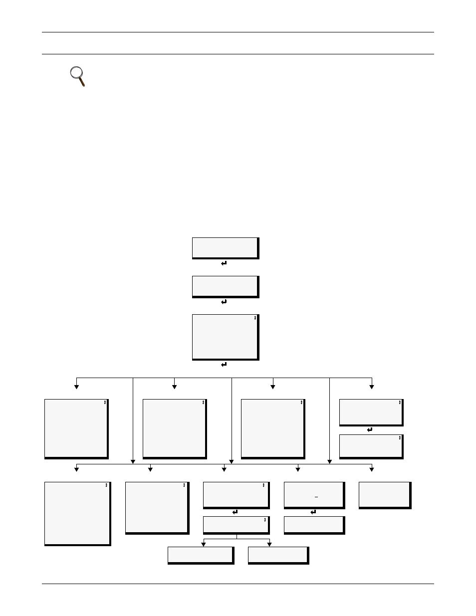
The View Status menu allows any user to view currently active alarms, monitoring data stored in the
alarm, event and trend logs, the status of all inputs and outputs, and the four pager numbers. The
arrows
↑↓
are used to scroll through the menu. The Enter
↵
key is used to select the menu item.
This section presents step-by-step instructions for each of the following options:
Figure 9 shows the main options available from the View Status menu.
Figure 9
Menu overview - View Status menu
NOTE
For ease of understanding, this section uses the LCD interface to illustrate most instructions,
except for features that are available only through the Service Terminal Interface. All Service
Terminal Interface screens appear in Appendix A - Service Terminal Interface.
• View Active Alarms
• View Trend Log
• View Pager Numbers
• View Alarm Log
• View Input Status
• View Operation
• View Event Log
• View Output Status
• View Control Status
Opening Screen
LIEBERT AC8
DD-MON-YY HR:MM:SS
VX.XXX.X
PRESS
↵
=STATUS/SETUP
Main Menu
> VIEW STATUS
SYSTEM AND CONTROL
↑↓
=NEXT
↵
=SELECT
View Status
VIEW ACTIVE ALARMS
VIEW ALARM LOG
VIEW EVENT LOG
VIEW TREND LOG
VIEW INPUT STATUS
VIEW OUTPUT STATUS
VIEW PAGER NUMBERS
VIEW OPERATION
VIEW CONTROL STATUS
View Active Alarms
View Alarm Log
View Event Log
View Trend Log
> ACTIVE ALARM 22/22
SENSOR_1
101.0 DEG
HIGH SETPOINT ALARM
SENSOR_2
------ DEG
SENSOR PROBLEM
DEVICE_7
ALARM
CONTACT OPEN
BATTERY
CHECK BATTERY
See
Section
> ALARM RECORD 99/99
SENSOR_2
80.0 DEG
HIGH SETPOINT ALARM
29-AUG-05
09:29:10
MODEM
INTERNAL FAULT
29-AUG-05
09:20:00
DEVICE_8
ALARM
CONTACT CLOSED
29-AUG-05
07:30:00
See
Section
> EVENT RECORD 99/99
PAGER
UNSUCCESSFUL PAGE
07-MAY-05
10:07:00
DEVICE_1
FORCE ON
CONTACT CLOSED
06-MAY-05
02:47:03
DEVICE_8
ON
CONTACT OPEN
05-MAY-05
05:22:17
See
Section
SENSOR TO VIEW?
> SENSOR_1
SENSOR_2
SENSOR_3
SENSOR_4
See
Section
> TREND LOG 100/100
SENSOR_1
75.4 DEG
NORMAL
28-AUG-05
15:45:51
View Input Status
View Output Status
View Pager Numbers
View Operation
View Control Status
INPUT
/
STATUS
> SENSOR_1 +80.00 DEG
SENSOR_2 ------ DEG
SENSOR_3
SENSOR_4 +79.50 RH
DEVICE_1
NORMAL
DEVICE_2
ALARM
DEVICE_3
EVENT
DEVICE_4
ALARM
DEVICE_5
ALARM
DEVICE_6
EVENT
DEVICE_7
NORMAL
DEVICE_8
NORMAL
See
Sec.
OUTPUT / STATUS
> DEVICE_1 ALARM
DEVICE_2 OPERATING
DEVICE_3 OPERATING
DEVICE_4 OPERATING
DEVICE_5 STANDBY
DEVICE_6 NOT USED
DEVICE_7 NOT USED
DEVICE_8 NOT USED
See
Sec.
PAGER TO VIEW?
> PAGER NUMBER 1
PAGER NUMBER 2
PAGER NUMBER 3
PAGER NUMBER 4
See
Sec.
SELECT ZONE FOR
VIEWING
>
ZONE 1
See
Sec.
CONTROL STATUS
RELAY 1
OFF
RELAY 2
OFF
See
Sec.
VIEW PAGER NUMBER
VIEW PAGER PIN
AUTO SEQUENCING ON
DAY 01 OF 02 (08:55)
STANDBY TESTING OFF
PAGER 1 NUMBER
9,,18005551212##
PAGER 1 PIN
01234567891011121344
View Status options