Efault, Ettings, Uick – Emerson Autochangeover Controllers AC8 User Manual
Page 125: Eference, Uide, Table 35, Ac8 - default settings for inputs and outputs, B - d
Setup Menu
117
A
PPENDIX
B - D
EFAULT
S
ETTINGS
Q
UICK
R
EFERENCE
G
UIDE
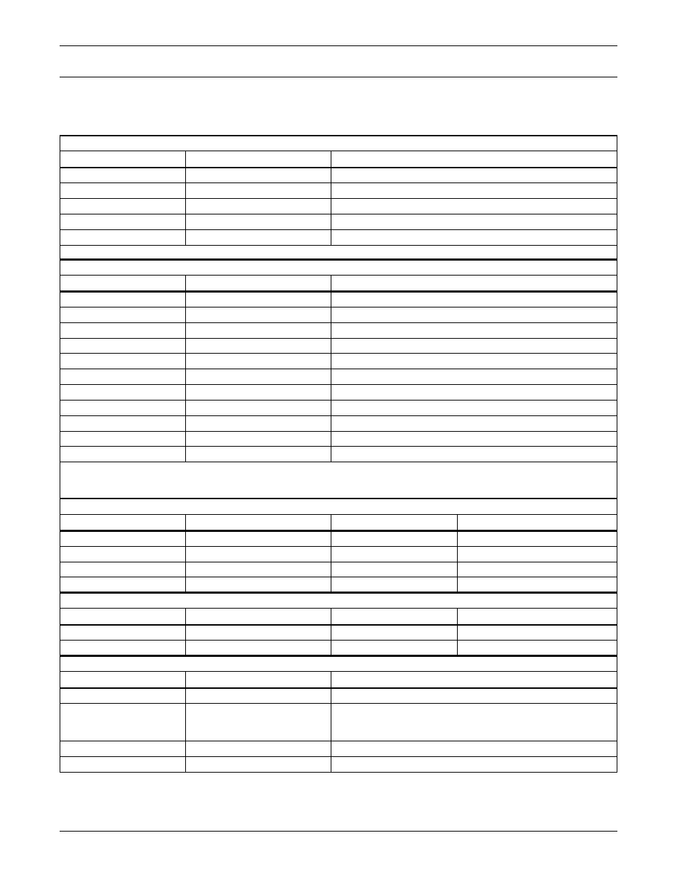
This appendix provides a quick reference to default settings for the AC8. These settings also appear
throughout the manual.
Table 35
AC8 - default settings for inputs and outputs
DEFAULT SETTINGS - DIGITAL INPUTS (FROM Table 15)
Feature
Default
Other Options
LABEL
DEVICE_1 - DEVICE_8
Any name (up to eight characters)
NORM OPEN/CLOSE
NO (Normally open)
NC (Normally closed)
ALARM/EVENT
AL (Alarmable)
EV (Event)
LATCHED
L (Latched) / Y (Yes)*
NL (Unlatched) / N (No)*
DELAY
00:01 (1 second)
Any time (in minutes and seconds) from 00:00 to 99:59
* NOTE: Different abbreviations are used to designate a digital input as Latched (L/Y) or Unlatched (NL/N) in Select Input/Set Inputs screens.
DEFAULT SETTINGS - ANALOG SENSOR INPUTS (FROM TABLE 17)
Feature
Default
Other Options
CONNECTED*
N (Not connected)*
Y (Connected)**
LABEL
SENSOR_1 - SENSOR_4
Any name (up to eight characters)
UNITS
DEG
Any units (up to three characters)
4 mA
+045.0
Can define up to two decimal places—e.g., -99.99
20 mA
+096.0
Can define up to two decimal places—e.g., +99.99
OFFSET
+000.0
Can define up to two decimal places—e.g., +00.00
ALARM/EVENT
AL (Alarmable)
EV (Event)
LATCHED
N (Unlatched)
Y (Latched)
LOW SETPT
+0050.0
Can define up to two decimal places—e.g., -999.99
HIGH SETPT
+0090.0
Can define up to two decimal places—e.g., +999.99
SENSOR DELAY
00:01 (1 second)
Any time (in minutes and seconds) from 00:00 to 99:59
* If a sensor is configured as N (Not connected), the display will show an empty reading (blank spaces).
** If a sensor is configured as Y (Connected) and is functioning properly, the display will show a reading.
If the connected sensor is not functioning properly, the display will show dashes (
------
) indicating a problem.
DEFAULT MAPPINGS - DIGITAL INPUTS TO CONTROL RELAYS (FROM TABLE 30)
Digital input
Mapping to control relay:
Digital input
Mapping to control relay:
Device_1
(none)
Device_5
(none)
Device_2
(none)
Device_6
(none)
Device_3
(none)
Device_7
(none)
Device_4
(none)
Device_8
(none)
DEFAULT MAPPINGS - ANALOG INPUTS TO CONTROL RELAYS (FROM TABLE 31)
Analog input
Mapping to control relay:
Analog input
Mapping to control relay:
Sensor_1
(none)
Sensor_3
(none)
Sensor_2
(none)
Sensor_4
(none)
DEFAULT SETTINGS - DIGITAL OUTPUTS (FROM Table 19)
Feature
Default
Other Options
NORM OPEN/CLOSE
NO (Normally open)
NC (Normally closed)
MODE*
Outputs 1-2:
Outputs 3-4:
Outputs 5-8:
OP (Operating)
ST (Standby)
NU (Not Used)
OP (Operating)
ST (Standby)
NU (Not Used)
IN ALARM
E (Enable)
D (Disable)
EMERG OP
E (Enable)
D (Disable)