Control transformer and fuses, Fan safety switch, High-temp sensor – Emerson Liebert Challenger With Liebert iCOM Control 3000/ITR User Manual
Page 43: Smoke detector, Water detection sensor, Figure 21 liebert leak detection units, Warning
Component Operation and Maintenance
37
Control Transformer and Fuses
The control system is divided into four separate circuits. The control voltage circuits are individually
protected by fuses located on the transformer/fuse board. If any of the fuses are blown, first eliminate
shorts, then use spare fuses supplied with unit. Use only type and size of fuse specified for your unit.
The small isolation transformer on the board supplies 24 volts to the main control board. The trans-
former is internally protected. If the internal protector opens, the transformer/fuse board must be
replaced. Also check the control voltage fuse on the main control board before replacing the trans-
former/fuse board.
Fan Safety Switch
The Fan Safety Switch is located in the low voltage compartment and consists of a diaphragm switch
and interconnecting tubing to the blower scroll. The Fan Safety switch is wired directly to the control
circuit to activate the alarm system if the airflow is interrupted
High-Temp Sensor
The optional high-temp sensor is a bimetal-operated sensing device with a normally closed switch.
This device will shut down the entire unit when the inlet air temperature exceeds a preset point. It is
connected between Terminals 1 and 2 at Plug P39.
Smoke Detector
The optional smoke detector power supply is located on the base of the upflow units, and at the top of
downflow units. It is constantly sampling return air through a tube. No adjustments are required.
Water Detection Sensor
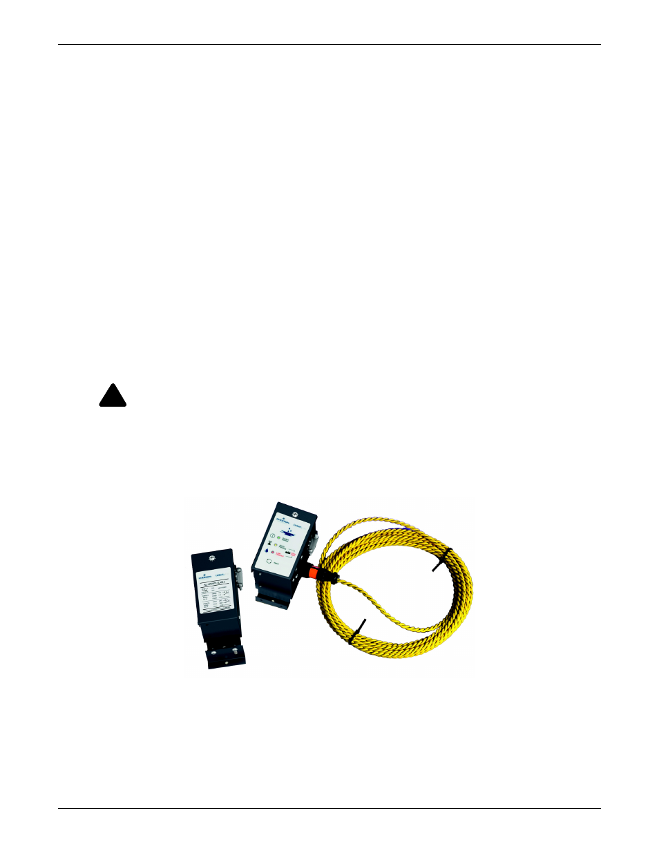
The optional water detection devices available are a point leak detection sensor and a zone leak detec-
tion kit.
Figure 21 Liebert leak detection units
The point leak detection sensor provides leak detection at a critical point. A simple two-wire connec-
tion signals the alarms at a Liebert environmental unit or at a monitoring panel. Run wires to the
Liebert unit and connect them to terminals 24 and 51, 55 or 56. Use NEC Class 2, 24V wiring. The
sensor contains a solid state switch that closes when water is detected by the twin sensor probes. The
sensor is hermetically sealed in all thread PVC nipple and is to be mounted where water problems
may occur. The sensor should be located 6-8 feet (2-2.5m) from the environmental control unit in a
wet trap or near a floor drain. It should not be mounted directly under the unit.
!
WARNING
Risk of fire or explosion. Can cause injury or death.
Do not use near flammable liquids or for flammable liquid detection.
Liebert Liqui-tect Point
Leak Detection Sensor
LT460 Zone Leak Detection Kit