6 wiring for unit-to-unit communications—u2u, 1 liebert icom u2u ethernet network, Table 2 sample liebert icom network configurations – Emerson Liebert Challenger With Liebert iCOM Control 3000/ITR User Manual
Page 23: 2 wiring a liebert icom u2u network, Small displays, Wiring for unit-to-unit communications—u2u, Liebert icom u2u ethernet network, Wiring a liebert icom u2u network, Table 2, Sample liebert icom network configurations
Liebert iCOM Display Components and Functions
17
4.6
Wiring for Unit-to-Unit Communications—U2U
The Liebert Challenger 3000/Liebert Challenger ITR with Liebert iCOM comes from the factory wired
for stand-alone operation. Multiple units can be set up in a network for efficiency, ease of operation
and easier control.
4.6.1 Liebert iCOM U2U Ethernet Network
The Liebert iCOM U2U network must be isolated from other network traffic. The network switch(es)
that connect Liebert iCOM controls need to be dedicated to supporting only Liebert iCOM communi-
cation. The U2U network cannot be connected to the building or IT network. If network communica-
tion is ever lost (failed network switch, etc.), all Liebert iCOM-controlled cooling units will continue to
operate as independent units.
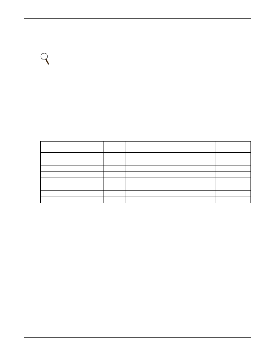
The Liebert iCOM control can support up to 64 nodes on one network. An input/output board, large
display and large wall-mount display are each considered one node. No more than 32 nodes may be
input/output boards (32 cooling units). A small display is not considered a node. Small displays con-
nect directly to input/output boards that do not have large displays attached to them. The following
table illustrates how a network can be configured.
Network communication can be configured during system startup by a Liebert-trained technician. For
technical issues contact:
Liebert Technical Service
1050 Dearborn Drive
Columbus, Ohio 43235
Telephone: 1-800-LIEBSRV (1-800-543-2778)
E-Mail:
4.6.2 Wiring a Liebert iCOM U2U Network
Small Displays
Two cooling units, each with a small display: To network two cooling units, each with a small
display, connect a crossover CAT5 cable between the P64 connectors on each cooling unit’s Liebert
iCOM input/output board. A network switch is not needed, because the small display connects
directly to the Liebert iCOM.
Three or more units with small displays: To network three or more cooling units, each equipped
with a small display, connect a straight-through CAT5 Ethernet cable from the P64 connector on each
cooling unit’s Liebert iCOM input/output board to a common network switch (see Figure 13).
NOTE
U2U connections can be set up to link these units: Liebert Challenger 3000, Liebert Challenger
ITR, Liebert DS and Liebert CW. Each unit must be equipped with a Liebert iCOM.
Table 2
Sample Liebert iCOM network configurations
Sample
Configuration
Input/Output
Boards
Large
Displays
Small
Displays
Wall Mount
Large Displays
Private Switch
Required
Ports Required
on Switch
1
2
0
2
0
No
NA
2
2
0
2
1
Yes
3
3
3
0
3
0
Yes
3
4
2
1
1
0
Yes
3
5
8
4
4
1
Yes
13
6
32
32
0
0
Yes
64
7
32
27
5
5
Yes
64
8
32
0
32
32
Yes
64