8 0-10 v module window guide – ProSoft Technology BM-xx00-RM1K User Manual
Page 42
Advanced User Interface for PC
Page 42 of 48
ProSoft Technology, Inc.
April 21, 2015
9.8
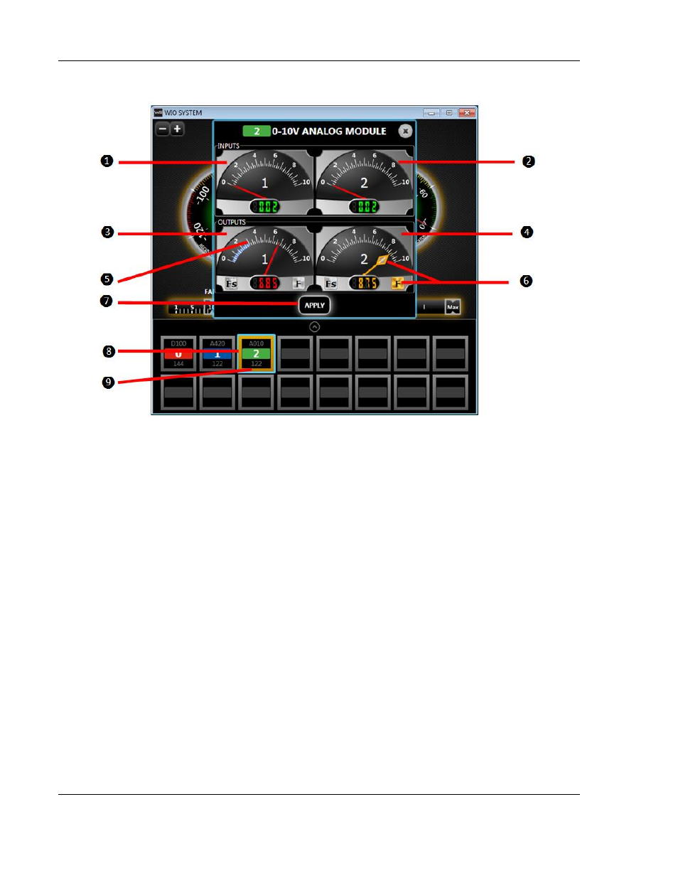
0-10 V Module Window Guide
1.
Input 1 Status
2.
Input 2 Status
3.
Output 1 Status (Red Needle)
4.
Output 2 Status (Red Needle)
5.
FailSafe
a.
Without the User Interface (default), the output reports last known value when RF or I/O failure
occurs.
b.
Click the
“Fs” button and specific value can be assigned for output when RF or I/O failure
occurs: Use the Blue Triangle needle to set specific value. Set value is indicated in blue on dial
and numeric display.
c.
Apply button
– must click apply for changes to take effect.
6.
Force Output Button
a.
Click the
“F” button to manually force a specific output. Forcing an output bypasses normal
signal: Use the Yellow needle for adjustment.
b.
To disable forcing an output, click
“F” again to deactivate force mode.
c.
Closing the User Interface or unplugging the mini USB cable will automatically deactivate any
forced output(s).
7.
Apply button
– must click in order for changes to take effect.
8.
Blue border indicates selected I/O Module.
9.
Orange border indicates forced output is active.