8diagnostics – ProSoft Technology BM-xx00-RM1K User Manual
Page 33
Diagnostics
ProSoft Technology, Inc.
Page 33 of 48
April 21, 2015
8
Diagnostics
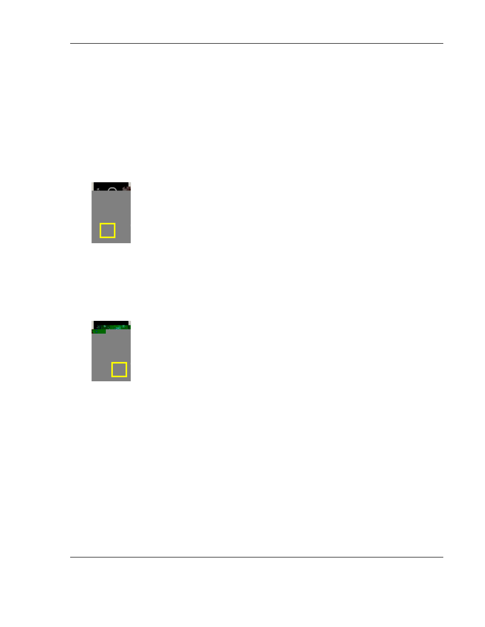
8.1
Radio Module
1. RF LED (Left):
2. Green: RF traffic / data rate
a. Yellow: RF link failure
i.
Indication of RF link failure after 10 second RF timeout and showing
the Wireless I/O System is operating in FailSafe mode.
ii.
RF Link Alarm Output (P2 - NPN) is triggered to report failure status.
iii.
Check antenna connections and power at both Radio stations.
iv.
Check for clear line of sight, any obstruction in the path may
negatively impact RF signal quality.
3. I/O LED (Right):
a. Green: Modules detected, I/O ok
b. Red: I/O link failure
i.
Visual indication of I/O link failure.
ii.
I/O Link Alarm Output (P1
– NPN) is triggered to report failure status.
iii.
Functioning I/O will perform normally under alarm condition.
iv.
Any mismatched I/O Modules will be put to FailSafe mode.
v.
Check for I/O mismatch
– check each pair of Modules is set to its
own ID.
vi.
Check both Radio Stations have matching Modules.
vii.
Check DataRail condition
– check for any sign of wear, debris,
oxidation.
viii.
For signal integrity verification, perform Remote Loop Back
diagnostics by wiring the based on diagram below.