4 main window guide – ProSoft Technology BM-xx00-RM1K User Manual
Page 38
Advanced User Interface for PC
Page 38 of 48
ProSoft Technology, Inc.
April 21, 2015
9.4
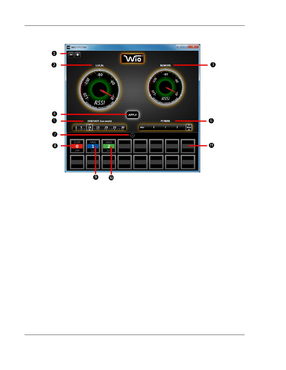
Main Window Guide
1.
Screen Size
– Zoom In/Out
2.
Local RSSI (Received Signal Strength Indicator)
a.
This level indicates the incoming signal strength received from remote Radio.
3.
Remote RSSI
a.
This level indicates the outgoing signal strength from local Radio to remote Radio.
b.
Adjusting Transmit Power will impact Remote RSSI.
4.
Apply button
– Appears when any setting is modified. Must click Apply in order for any changes to
become effective on the local device.
5.
RF Link Alarm Output and Operating in FailSafe mode is triggered by this RF timeout interval.
a.
10-second default RF timeout (1-second increments: 2 to 30 second range).
6.
Transmit Power Adjustor
– for optimization of power level and power consumption.
7.
I/O Module Tray
– this tray displays all connected I/O Modules - use the arrow button to expand or
minimize I/O Module Tray view.
8.
Green color code indicates 0-10 V Analog Module.
9.
Blue color code indicates 4-20 mA Analog Module.
10. Red color code indicates Digital Module.
11. Empty Module Slot