ProSoft Technology AN-X-PB User Manual
Page 34
Page
28
AN-X-PBSLV
January 2008
Module Name
The first line in the file is the module name, used to create tags that can
be imported into RSLogix 5000.
The first field contains the keyword ClxExp. The second field contains
the name you gave the module when you configured in in RSLogix 5000.
Example:
ClxExp, ANX
I/O Data
The file has three data definition sections, one for ControlLogix output
data, one for input data, and one for status input data. The sections are
identified by a line that consists of a keyword, either “DataOutput”,
“DataInput” or “StatusInput”.
Each section can contain up to 64 data definition entries.
Each definition consists of the offset into the data section, the
PROFIBUS node number, the PROFIBUS data area and offset, the item
count, the data type, and a ControlLogix tag name.
The first field in each row or line is the offset into the data section and is
optional. If you do not want to manually assign data offsets, leave the
offset blank.
The PROFIBUS node number can range from 1 to 125.
The PROFIBUS data area consists of an I or an O for PROFIBUS input
or output data, a slash, and a byte offset into the PROFIBUS input or
output data for that node. Offsets are always byte offsets, independent of
the data type.
The count is the number of consecutive data items to be mapped for that
node. The units are determined by the data type.
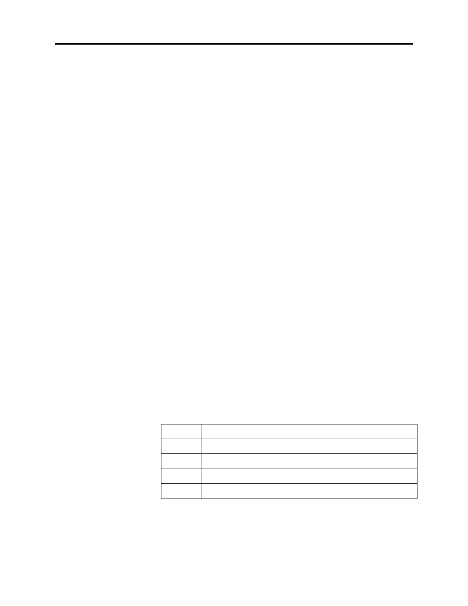
The type can be one of:
Type
Description
U8
8-bit unsigned integer, 0 to 255
S8
8-bit signed integer, -128 to 127
U16
16-bit unsigned integer, 0 to 65535
S16
16-bit signed integer, -32767 to 32767
Each element of type S8 or U8 is mapped to an INT in the ControlLogix.
Bytes are not packed into the high byte and low byte of integers.