ProSoft Technology MVI94-MCM-MHI User Manual
Page 76
Reference
MVI94-MCM ♦ Flex I/O Platform
User Manual
Serial Communications Modbus Communication Module
Page 76 of 109
ProSoft Technology, Inc.
March 29, 2011
The module and the processor constantly monitor input and output images. How
does either one know when a new block of data is available? Recognizing a
change in the header information of the image (word 0) solves the problem. For
example, when the module recognizes a different value in the first word of the
output image, new data is available from the processor. When the processor
recognizes a new value in the first word of the input image, new data is available
from the module. This technique requires the storage of the previously processed
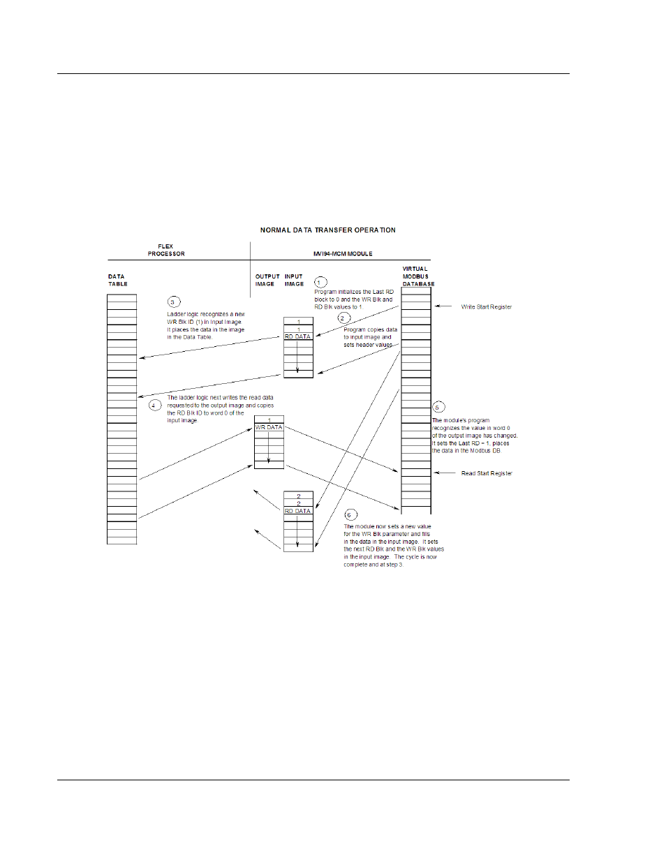
data block identification code. The following illustration shows the normal
sequence of events for data transfer:
The steps outlined in the diagram above are discussed below:
1 During program initialization, the write and read block identification codes are
set to one. The last block read variable is set to zero.
2 The program copies the first six-word block of the virtual Modbus database
starting at the user defined BT Read Start Register to the input image (words
2 to 7). It then sets the current read block code in word 1 of the input image.
To "trigger" the write operation, the program places the current write block
code into word 0 of the input image.
3 The Flex processor recognizes a new value in word 0 of the input image
(based on the last_read_block_code not equal to read_block_code) in its
ladder logic. The ladder logic computes the offset into the file based on the
following formula: