ProSoft Technology MVI94-MCM-MHI User Manual
Page 75
MVI94-MCM ♦ Flex I/O Platform
Reference
Serial Communications Modbus Communication Module
User Manual
ProSoft Technology, Inc.
Page 75 of 109
March 29, 2011
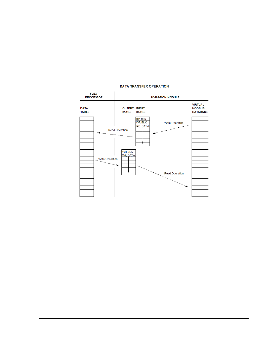
5.3.3 Data Transfer
Data is transferred over the backplane using the module’s input and output
images. The module is configured with an eight-word input image and a seven-
word output image. The module and the processor use these images to page
data and commands. The input image is set (written) by the module and is read
by the processor. The output image is set (written) by the Flex processor and
read by the module. The following diagram shows this relationship.
The module’s program is responsible for setting the block identification code
used to identify the data block written and the block identification code of the
block it wants to read from the processor. User configuration information
determines the read (BT Read Start Register) and write (BT Write Start Register)
locations in the virtual Modbus database and the amount of data transferred (BT
Read Register Count and BT Write Register Count). Each read and write
operation transfers a six-word data area. The read operation (from the processor
to the module) contains a two-word header that defines the block identification
code of the read data and the block identification code of the next write block
requested. These identification codes are in the range of 0 to 666. A value of
zero indicates that the block contains no data and should be ignored. The first
valid block identification code is one and refers to the first block of six words to
be read or written.