ProSoft Technology MVI56-BAS User Manual
Page 95
MVI56-BAS ♦ ControlLogix Platform
Using DH-485 Communications
BASIC Module (DB/BAS Compatible)
User Manual
ProSoft Technology, Inc.
Page 95 of 234
December 13, 2011
8.2
Writing to a Remote DH-485 SLC Data File (CALL 28)
Ladder logic is required to transfer data from the local ControlLogix rack to a
remote DH-485 SLC data file using the MVI56-BAS through CALL 28.
The source of the data in the local SLC processor is either the CPU output image
file, Class 3 MSG instruction, and/or an internal string in the within the MVI56-
BAS module.
The data transfer procedure is described below:
Step 1: Run CALL 28 to set up the data transfer parameters.
Step 2: The ladder logic sets output file word 0, bit 11 to inform the MVI56-BAS
that the data is ready to be transferred.
Step 3: The MVI56-BAS transfer the data from the ControlLogix processor to the
remote DH-485 SLC data file.
Step 4: The MVI56-BAS moves the transfer status into the input file word 1, bits
0 to 7. It then sets input file word 0, bit 11 to inform the ControlLogix that the data
had been transferred.
Step 5: The ladder logic resets output file word 0, bit 11.
Step 6: The MVI56-BAS resets the input file word, bit 11.
The following example BASIC code shows the simplest possible example that
transfers data from the local SLC (source file = CPU output image file) to a
remote SLC DH-485 data file:
10 REM TRANSFERS DATA FROM THE CLX TO THE SLC REMOTE DATA FILE
20 PUSH 2, 5, 9, ASC( N), 0, 5, 20, 0, 0, 0: CALL 28: POP S
30 PRINT "S =", S,
130 GOTO 130
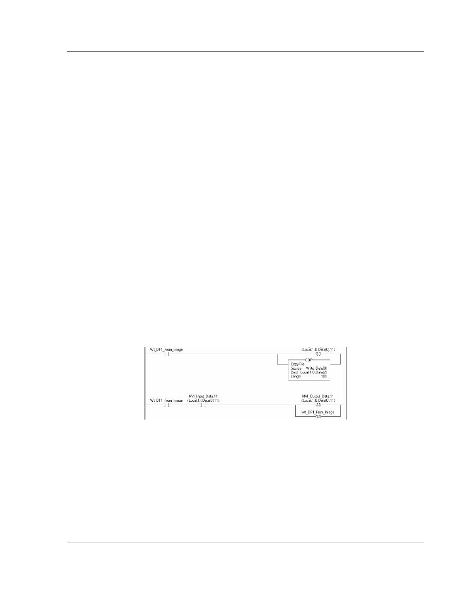
After the program is running, the following ladder example transfers data from the
Write_Data array to the remote SLC data file:
The following example BASIC code shows the simplest possible example that
transfers data from the local SLC (source file = Class 3 MSG) to a remote SLC
DH-485 data file:
10 REM TRANSFERS DATA FROM THE CLX TO THE SLC REMOTE DATA FILE
20 PUSH 2, 5, 9, ASC( N), 0, 5, 20, 1, 0, 0: CALL 28: POP S
30 PRINT "S =", S,