ProSoft Technology MVI56-BAS User Manual
Page 40
Backplane Data Transfer
MVI56-BAS ♦ ControlLogix Platform
User Manual
BASIC Module (DB/BAS Compatible)
Page 40 of 234
ProSoft Technology, Inc.
December 13, 2011
4.1
Data Transfer from Output Buffer to CLX Processor
The MVI56-BAS module output buffer can be used to transfer data to the
ControlLogix processor.
The first step is to move data to the output buffer using CALLs 24 and 25. These
CALLs convert BASIC floating point data into integer values truncating the
fractional part. The result is stored in the output buffer between addresses 0 and
231.
After the data has been moved to the output buffer, there are 2 ways to transfer it
to the ControlLogix; writing to the CLX input image file (CALL 54) or using MSG
instructions (CALL 57).
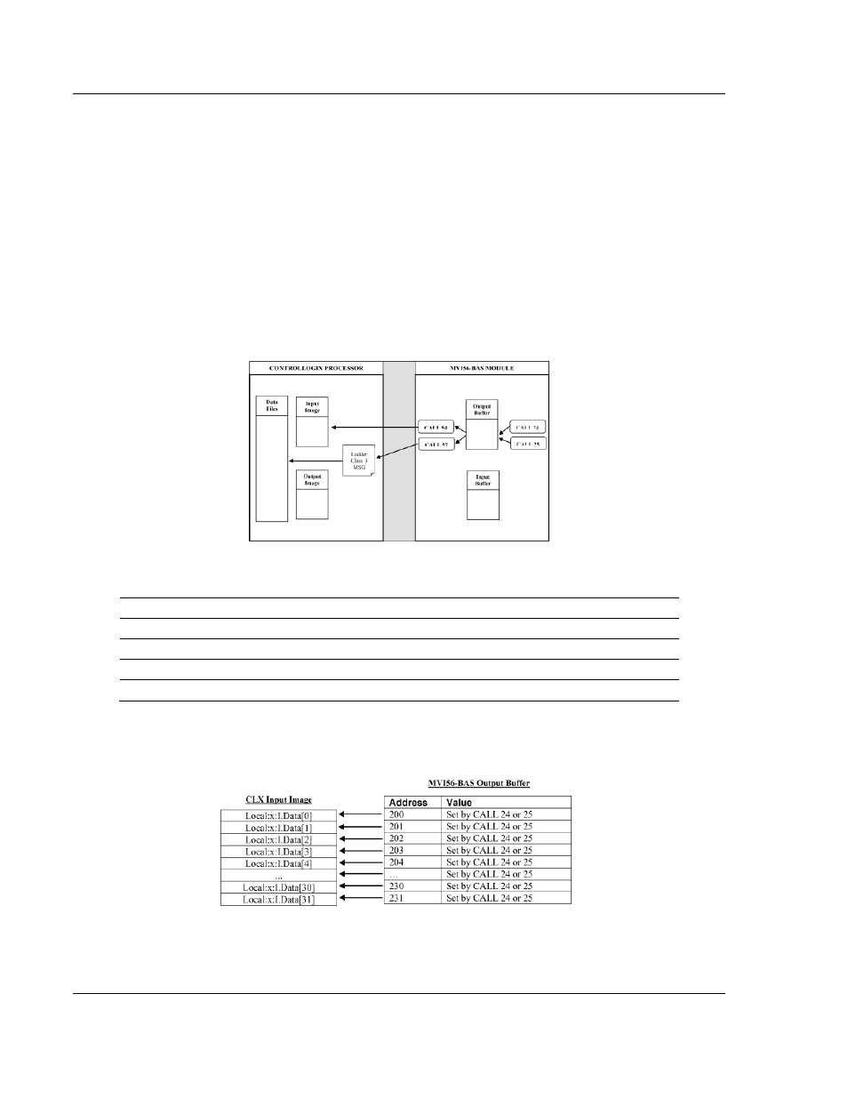
The following illustration shows how to transfer data between the MVI56-BAS
output buffer and the ControlLogix processor.
The output buffer is divided into areas depending on the destination of the data
transferred. The output buffer addressing is shown in the following table.
Address
Definition
0 to 39
DH-485 Common Interface File - data read by other devices
40 to 99
Reserved
100 to 199
Data read by the CLX using MSG instruction
200 to 231
Data transferred to the CLX Input Image file
CALL 54 transfers words 200 to 207 (8 words) from the module output buffer to
the CLX input image (Local:x:I.Data[ ]). No ladder logic is required to perform the
data transfer.