4 module installation – PLANET XGS3-42000R User Manual
Page 9
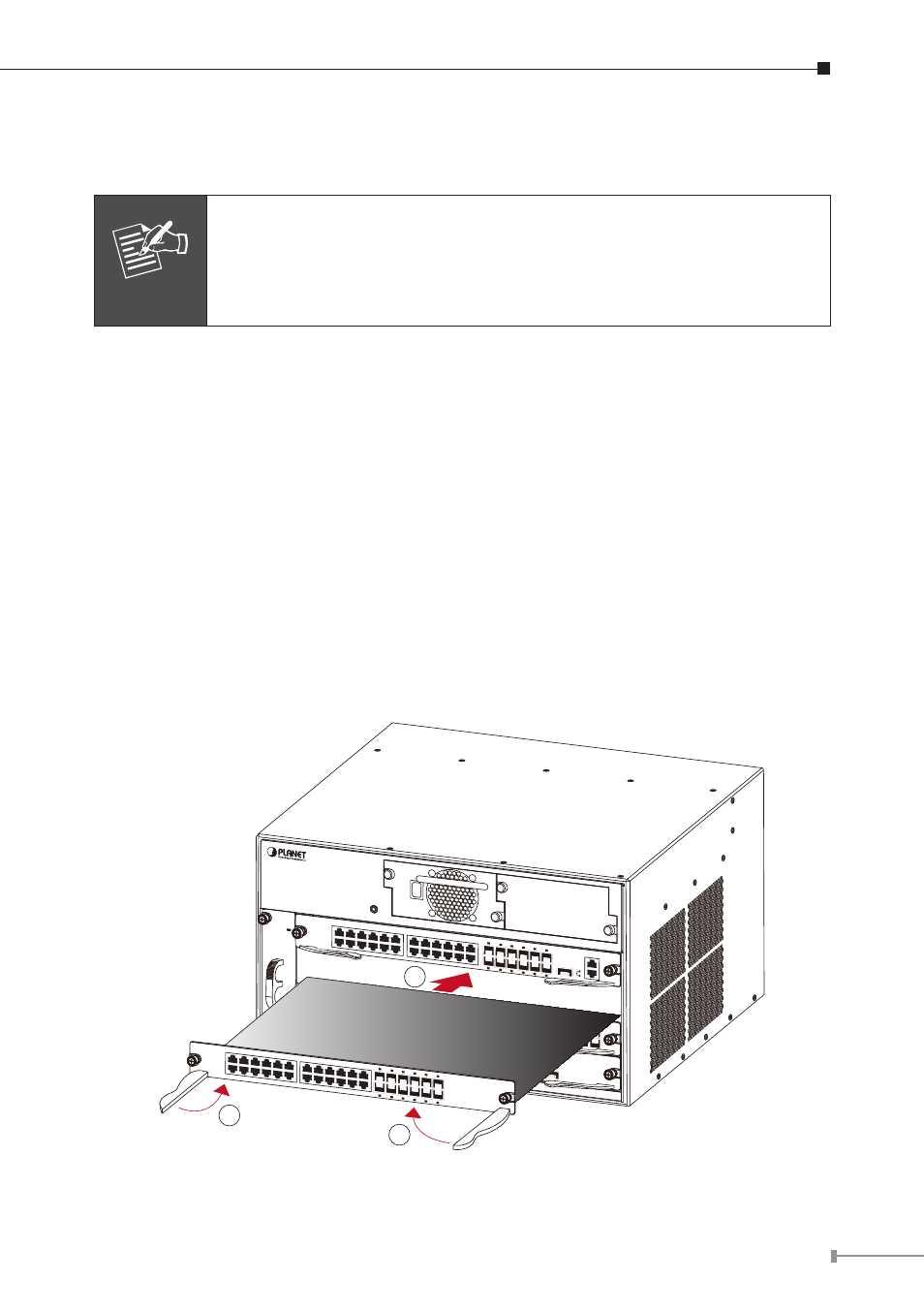
3.4 Module Installation
The installation procedure is the same for all cards, as shown below:
Note
Slot 1 should installed with Management Module before power on
the Chassis Switch otherwise the Chassis Switch will not operates
normally.
The Chassis Switch supports maximum 2 Management module for
purpose of management redundancy at slot 1 and slot 2.
Step1 Power down the XGS3-42000R (Hot-swapping is supported by optional
cards for the XGS3-42000R. However, for better convenience, it is
recommended to power down the XGS3-42000R before installing the
cards, if no module in the Chassis Switch is running).
Step2 Ensure proper grounding of the XGS3-42000R.
Step3 Put on an ESD wrist strap before contact with the Chassis Switch circuit,
and make sure the ESD wrist strap is connected securely to the ESD
connector in the Chassis Switch’s front panel.
Step4 Loosen the panel fasteners locking back plate counterclockwise and
remove the back plate.
Step5 Insert the optional module into the slot; you can use the metal handle
on the front plate of the module to ensure good contact. Then lock the
module with panel fasteners in the front plate.
2
1
3
4
XGS3-42000R
Layer 3 4-Slot Chassis Switch
O
I
XGS3-PWR-AC
ON
OFF
Fault
Output good
XGS3-M24GX
2
PWR RUN
Master FAN
1
4
3
6
5
8
7
10
9
12
11
14
13
16
15
18
17
20
19
22
21
24
23
25
XFP
25
Ethernet
LNK
ACT
Console, 9600, N, 8, 1
XGS3-S48GF
2
1
4
3
6
5
8
7
10
9
12
11
14
13
16
15
18
17
20
19
22
21
24
23
26
25
28
27
30
29
32
31
34
33
36
35
38
37
40
39
42
41
44
43
46
45
48
47
PWR RUN
XGS3-S4XG
1
LNK
ACT
2
LNK
ACT
3
LNK
ACT
4
XFP
XFP
XFP
XFP
LNK
ACT
XGS3-S24G
2
PWR RUN
1
4
3
6
5
8
7
10
9
12
11
14
13
16
15
18
17
20
19
22
21
24
23
14
13
16
15
18
17
20
19
22
21
24
23
1
2
2
14
13
16
15
18
17
20
19
22
21
24
23
Figure 3-3 Insert the optional module into the slot of XGS3-42000R