Avago Technologies ACPL-336J-000E User Manual
Page 8
8
Output Measurement
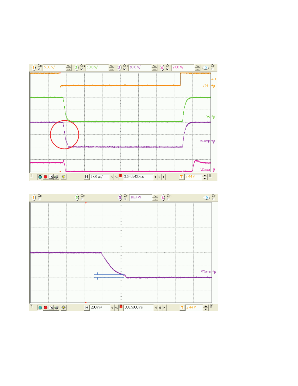
A sample of Input signal and various output waveforms are captured and shown in Figure 6, during IGBT gate turn-off
and turn-on instants. Default setup connection is used but with Q3 IGBT mounted. The IGBT used has a gate capaci-
tance equivalent to 10 nF. It is noticed that during normal working condition, the Desat pin voltage is much less than 7
V, and no Fault occurs.
Figure 6. ACPL-337J Input and output plus protection signal waveforms
For the exploded view, see Figure 7.
2 V
Figure 7. Exploded view of Active Miller Clamp pin waveform at turn-off
Figure 7 is the exploded view of the Miller Clamp pin-10 waveform during turn-off duration, it shows clearly that once
the detected Gate voltage drops below 2 V (typically), the Gate voltage is shunt and clamped to 0 V w.r.t. V
EE2
level dur-
ing the entire turn-off duration, to ensure that the Gate voltage has no chance of going above the turn-on threshold
level again.