Avago Technologies ACPL-336J-000E User Manual
Page 6
6
Preventing premature output turn-on through the use of UVLO
When IGBT is allowed to turn on immediately after gate voltage crosses the threshold voltage (typically 2~5V), the
collector emitter junction is operating at the linear region. This will cause high voltage built-up across the very same
junction, especially when the load is high. The conduction power dissipation (=load current * junction voltage) of the
device will be very high and it will be damaged if this power is higher than the allowable limit. To prevent high power
dissipation, the designer has to ensure that the turn-on of the IGBT is prohibited until the gate voltage has reached
a certain level where collector saturation can be reached, and usually this calls for a gate voltage to be >12 V. This is
achieved by including a UVLO circuit inside the ACPL-337J device. This UVLO circuit monitors the supply voltage at V
CC2
w.r.t. V
E
, and it will not allow output to be turn-on until V
CC2
voltage crosses the UVLO+ threshold, typically 12.3 V. The
UVLO protection circuit can be checked by varying V
CC2
supply voltage higher than or lower than the UVLO+ or UVLO-
threshold voltage, respectively. When V
CC2
supply voltage is lower than the UVLO- threshold, the /UVLO at pin 6 of U1
should send out a low level, w.r.t. Gnd.
Note:
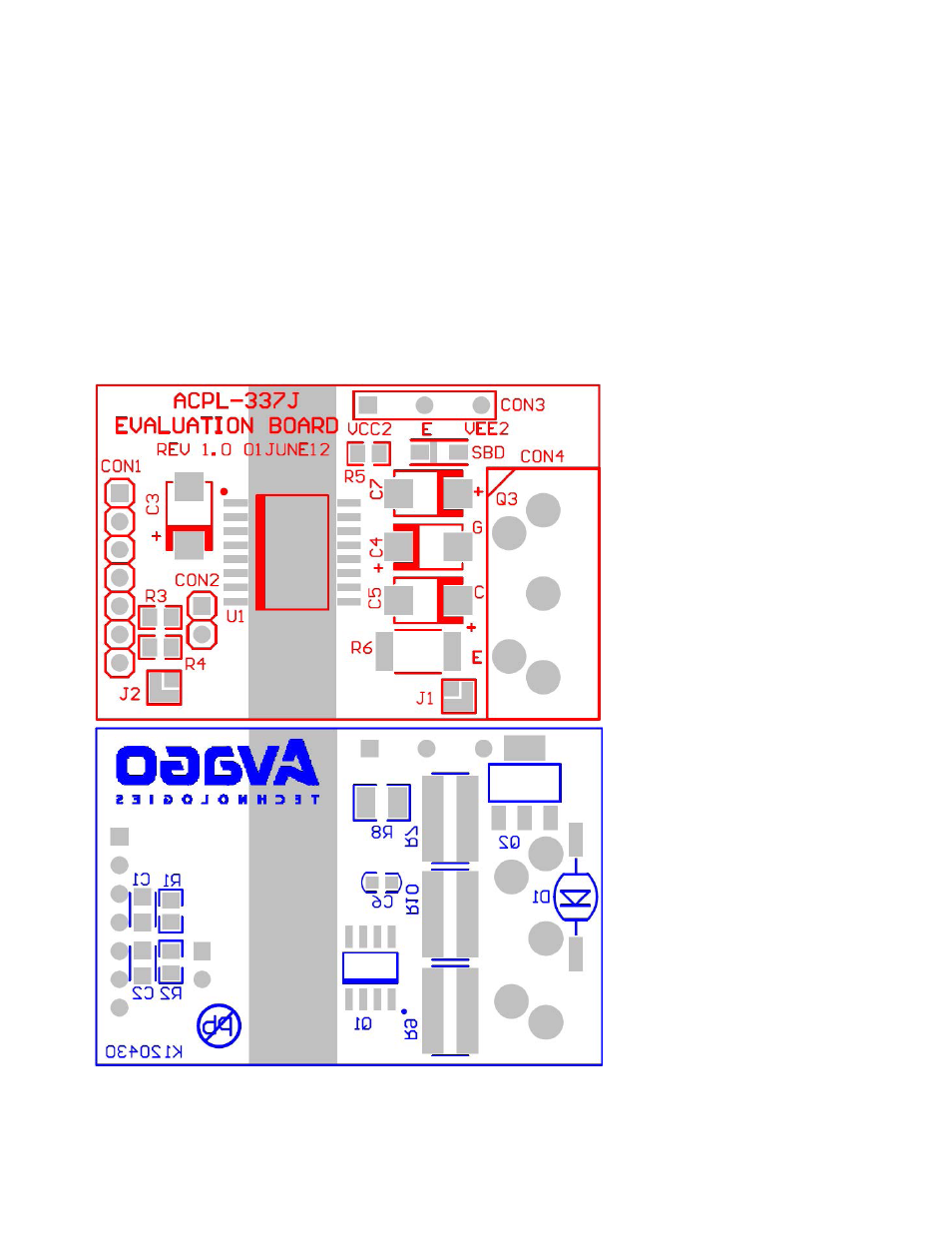
As can be seen on the board, the isolation circuitry (at the far left) is easily contained within a small area while adequate spacing is maintained for
good voltage isolation and easy assembly.
Figure 5. Top and bottom views of ACPL-337J evaluation board