Avago Technologies MegaRAID SAS 9286CV-8eCC User Manual
Page 6
LSI Corporation
- 6 -
MegaRAID SAS 9286CV-8eCC RAID Controller Quick Installation Guide
June 2012
MegaRAID SAS 9286CV-8eCC RAID Controller Quick Installation Guide
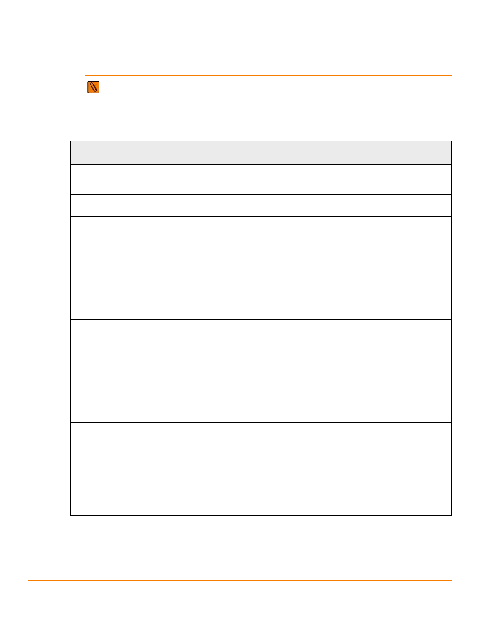
The following table describes the jumpers and the connectors on the MegaRAID SAS 9286CV-8eCC RAID Controller .
NOTE Pin 1 on the headers and the connectors is highlighted in red in
.
Table 1 Jumpers and Connectors
Jumper/
Connector
Type
Description
J1A1
Write pending LED header
2-pin connector
Connects to an LED that indicates when the data in the cache has yet to be
written to the storage devices. Used when the write-back feature is enabled.
J1A3
Global drive fault LED header
2-pin connector
Connects to an LED that indicates whether a drive is in a fault condition.
J1A4
x4 SAS Ports 4–7 external connector SFF-8088 x4 external mini SAS connector
Connects the controller by cable to SAS drives or SATA drives.
J1B1
x4 SAS Ports 0–3 external connector SFF-8088 x4 external mini SAS connector
Connects the controller by cable to SAS drives or SATA drives.
J2A1
Activity LED header
2-pin connector
Connects to an LED that indicates activity on the drives connected to the
controller.
J2A2
Advanced Software Options
Hardware Key header
3-pin header
Enables support for the Advanced Software Options features, which include
CacheCade™, FastPath, Recovery, and SafeStore™ disk encryption.
J2A4
I
2
O Mode jumper
2-pin connector
Installing this jumper causes the RAID controller to run in I
2
0 mode. The
default mode of operation is without the shunt and running in Fusion mode.
J2B1
Standard edge card connector
The RAID controller interfaces with the host system though a standard edge
card.
This interface provides power to the board and an I
2
C interface connected to
the I
2
C bus for IPMI.
J4A1
Serial EEPROM
2-pin connector
Provides controller information, such as the serial number, revision, and
manufacturing date. The default is no shunt installed.
J4A2
LSI test header
2-pin header
Reserved for LSI use.
J5A1
Serial Universal Asynchronous
Receiver/Transmitter (UART)
connector for the Expander
4-pin connector
Reserved for LSI use.
J5B1
DDR3 Board-to-board connector
240-pin connector
Connects the RAID controller to the CVFM03 module.
J6A1
Serial UART connector for the
Expander
4-pin connector
Reserved for LSI use.