Infinity, Tablier infinity, Tablier sincerity – MAAX AIGO 7236 User Manual
Page 20: Faldón infinity, Faldón sincerity
20
iNFiNitY
tM
apron
607 / 100201
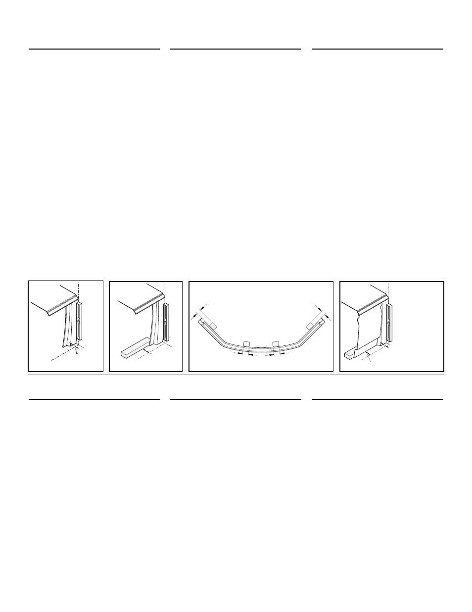
Locate bathtub in its exact location.
Lean level against bathtub and trace a
vertical line down to the floor. Fig. 19.1.
On the floor, trace a line perpendicular to
the one on the wall, 1" from the bathtub
Fig. 19.1.
Align the apron extension with the vertical
line; pivot the base of the extension
towards the inside of the bathtub down to
the 1" line. When extension is aligned with
the top of the bathtub and the line on the
floor, fasten it to the wall.
Using the line on the floor as a guide,
position blocks at 2 5/8" under the bathtub.
Fig. 19.2.
Fasten blocks to floor respecting distances
shown in Fig. 19.3.
Screw bottom of apron into blocks and
finish with screw covers. Fig. 19.4.
SiNceritY™ apron
624 R / 624 L / 100209-R / 100209-L
Left and right
Screw the extensions to the wall by
supporting them on a level positioned 1/4"
from the edge of the bathtub (Fig. 20.1a).
Screw in two #8 1 1/2" wood screws per
extension. Fig. 20.1.
Install a wood support (A) permanently
under the central part of the bathtub in
order to maintain it at the same height
(Dimension C
3
) as indicated in the table on
page 8 (Fig. 20.2).
Note: the wood support
must not get in the way of the plumbing /
valving.
Temporarily install the access hatch and
the apron (Fig. 20.3).
Place a mark on the floor before each
anchor hole located at the bottom of the
access hatch and the apron (Fig. 20.3).
Remove the access hatch and the apron.
tablier iNFiNitY
Mc
607 / 100201
Placez la baignoire dans son empla cement.
Appuyez le niveau contre la baignoire et tracez
une ligne verticale jusqu’au plancher. Fig. 19.1.
Sur le plancher, tracez une ligne per pen-
diculaire à celle déjà tracée sur le mur, à 1"
de la baignoire. Fig. 19.1.
Alignez l’extension du tablier avec la ligne
verticale au mur et faites glisser l’extension
vers l’intérieur de la bai gnoire jusqu’à la
ligne de 1". Une fois l’extension alignée
avec le haut de la baignoire et la ligne au
sol, fixez-la au mur.
À partir de la ligne déjà tracée au sol,
positionnez les blocs à 2 5/8" de cette
ligne, sous la baignoire. Fig. 19.2.
Fixez les blocs selon la disposition illustrée
à la Fig. 19.3.
Vissez la base du tablier aux blocs et
couvrez avec les cache-vis pour la finition.
Fig. 19.4.
tablier SiNceritY
Mc
624 R / 624 L / 100209-R / 100209-L
Gauche et droit
Visser les extensions au mur en les
appuyant sur un niveau positionné à 1/4"
du rebord de la baignoire. Fig. 20.1a.
Visser deux vis à bois #8 x 1 1/2" par
extension. Fig. 20.1.
Fixer un renfort de bois (A) de façon
permanente sous la partie centrale avant
de la baignoire afin de la maintenir à la
même hauteur (Dimension C
3
) qu’indiqué
au tableau de la page 8. Fig. 20.2.
Note:
le renfort de bois ne dois pas nuire à la
plomberie / robinetterie.
Installer de façon temporaire la trappe
d’accès et le tablier. Fig. 20.3.
Marquer le sol vis-à-vis chaque trou
d’ancrage se trouvant dans le bas de la
trappe d’accès et du tablier. Fig. 20.3.
Retirer la trappe d’accès et le tablier.
Faldón iNFiNitY
Mc
607 / 100201
Colocar el baño en su posición exacta.
Colocar el nivel sobre el baño y trazar una
línea vertical hasta el piso. Fig. 19.1.
Sobre el piso, trazar una línea per pen dicular a
la línea ya trazada sobre la pared, sea a 1" del
baño. Fig. 19.1.
Alinear la alargadera del salpicadero con la
línea vertical en la pared y deslizarla hacia
el interior del baño hasta la línea de 1".
Después de alineada la alargadera con la
parte superior del baño y con la línea en el
piso, sujetarla sobre la pared.
Desde la línea ya trazada en el piso,
colocar los bloques a 2 5/8" de la línea, por
debajo del baño. Fig. 19.2.
Sujetar los bloques tal como ilustrado en
la Fig. 19.3.
Atornillar la base del salpicadero so bre los
bloques y cubrir los tornillos con cubretornillos
para acabado. Fig. 19.4.
Faldón SiNceritY
Mc
624 R / 624 L / 100209-R / 100209-L
izquierdo y derecho
Atornillar las extensiones a la pared
apoyándolas sobre un nivel situado a 1/4"
del borde de la bañera Fig. 20.1a. Fijar dos
tornillos para madera del #8 x 1 1/2" en
cada extensión. Fig. 20.1.
Fijar de modo permanente un refuerzo
de madera (A) bajo la parte central, por
delante de la bañera, para mantenerla a
la misma altura (Dimensiones C
3
) que se
indica en el cuadro de la página 8. Fig.
20.2.
Nota: el refuerzo de madera no debe
dañar las tuberías / griferías.
Instalar provisionalmente la trampilla de
acceso y el faldón. Fig. 20.3.
Marcar el suelo por delante de cada uno de
los agujeros de anclaje que se encuentran
en la parte inferior de la trampilla de
acceso y del faldón. Fig. 20.3. Retirar la
trampilla de acceso y el faldón.
2 5/8"
(67 mm)
3"
4"
3"
4"
1"
(25.4 mm)
2 3/8" (60 mm)
Bloc/Block 2 5/8"
1"
(25.4 mm)
2 5/8"
(67 mm)
3"
4"
3"
4"
1"
(25.4 mm)
2 3/8" (60 mm)
Bloc/Block 2 5/8"
1"
(25.4 mm)
2 5/8"
(67 mm)
3"
4"
3"
4"
1"
(25.4 mm)
2 3/8" (60 mm)
Bloc/Block 2 5/8"
1"
(25.4 mm)
Fig. 19.2
Fig. 19.3
Fig. 19.4
1" (25.4 mm)
Fig. 19.1