Connector jumpers to parallel sense wires -15, Gh 2-10), Ar. 2.4.2.3.4: pa – KEPCO RA 19-7B Operator Manual User Manual
Page 27
RA 19-7B 011409
2-15
2.4.2.3.4 PARALLEL CONFIGURATIONS USING EXTERNAL WIRES TO CONNECT SENSE LINES
IN PARALLEL AND EXTERNAL WIRES TO CONFIGURE REMOTE SENSING
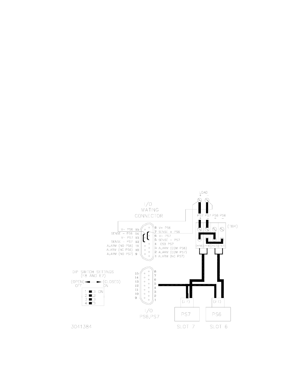
Figure 2-10 is a simplified diagram of a typical parallel configuration using remote sensing via
external wires to connect V(+) to S(+), V(–) to S(–) and jumpers connected to the I/O mating
connector to connect the sense leads in parallel. This configuration requires the following:
1. For each supply in parallel set DIP switch positions 1 and 2 to OFF (open) (see Figure 2-1).
2. For each DIP switch between parallel-connected slots, set DIP switch positions 3 and 4 to
OFF (open) (sense leads will be connected in parallel in steps 8 and 9) (see Figure 2-1).
3. For each DIP switch between parallel-connected slots, configure position 5 to connect the
current share bus by referring to PAR. 2.4.2.2.
4. Locate DIP switch(es) at both ends of the parallel group and set positions 3, 4, and 5 to OFF
(open) to isolate the group. (see Figure 2-1).
5. Configure Positions 6, 7, and 8 (alarms) of each DIP switch per PAR. 2.4.4.
6. Connect short jumper across I/O mating connector Sense (+) pins.
7. Connect short jumper across I/O mating connector Sense (–) pins.
8. Connect wire from I/O mating connector Sense (+) pin to V (+) at the load.
9. Connect wire from I/O mating connector Sense (–) pin to V (–) at the load.
FIGURE 2-10. TYPICAL PARALLEL CONNECTIONS, REMOTE SENSING USING I/O MATING
CONNECTOR JUMPERS TO PARALLEL SENSE WIRES