14 status flags, Table 3-1. status flags, 1 source power status flags – KEPCO HSM Series User Manual
Page 32: Status flags -8, Source power status flags -8, R. 3.14
3-8
HSMSERIES OPR 052912
and isolated from the ISHARE signal, so that it cannot affect the load share function if shorted.
The voltage level of this signal is generated with respect to the negative sense return (pin 19).
3.14
STATUS FLAGS
HSM power supplies provide electrical indication of the status of various critical functions includ-
ing source power status, output status, fan status and overtemperature condition. Signal indi-
cation is obtained via four sets of Form C dry relay contacts accessed via the I/O connector; all
three contacts are provided to the user, permitting the selection of either normally-open (NO),
normally-closed (NC) or both for any application (refer to Table 2-2). The definition of "normal"
in this instance refers to the status of the contacts when the HSM is powered and operating nor-
mally (no fault); status flag outputs remain valid even when source power is removed. These
relay contacts are SELV and are isolated from each other and from the output by 100V d-c to
permit flexibility in application. A description of the function of each status signal follows. Table
3-1 indicates the condition of statusflags and indicators for normal, fault, and no power condi-
tions.
3.14.1
SOURCE POWER STATUS FLAGS
Monitors available source voltage to determine if sufficient energy is available to sustain rated
output for normal operation. These signals indicate a fault condition until the bulk voltage is
greater than 390V d-c. Once the bulk voltage reaches 390V d-c ( indicating that the PFC boost
converter is operating and assuring that full ride-through time is available at rated load) these
signals revert to "normal" (see Table 3-1). These signals will indicate a fault a minimum of 5
milliseconds prior to loss of output regulation due to source power loss, providing a transparent
source power ride-through time of 21.5 milliseconds; POWER STATUS is not reset until the bulk
d-c again reaches 390V d-c; see Figure 3-6 for timing relationships.
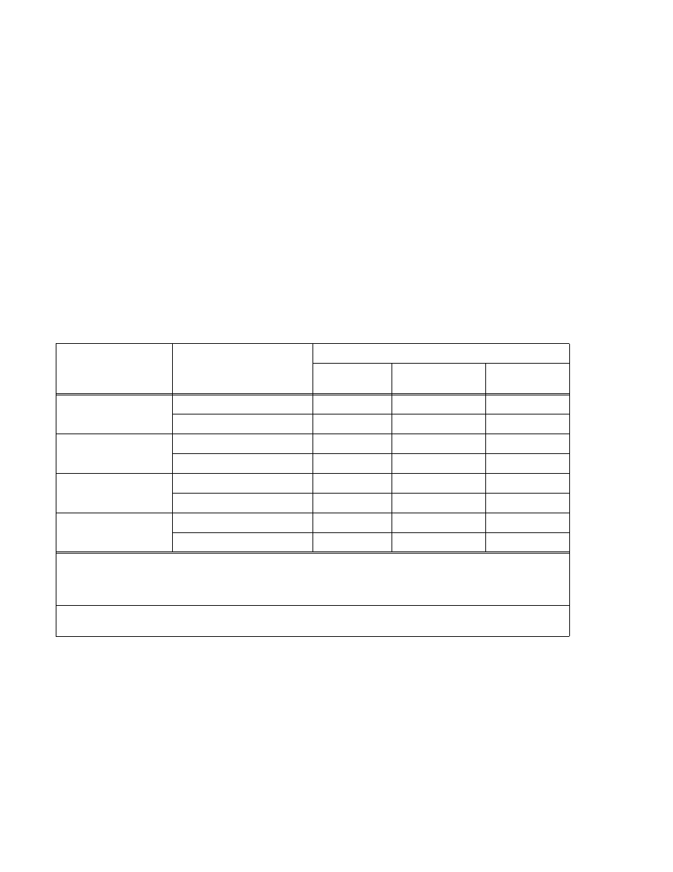
TABLE 3-1. STATUS FLAGS
CONDITION
SIGNAL
STATUS **
NORMAL *
FAULT DETECTED
NO POWER
APPLIED
SOURCE POWER
STATUS
SOURCE POWER STATUS NC
CLOSED
OPEN
OPEN
SOURCE POWER STATUS NO
OPEN
CLOSED
CLOSED
OUTPUT STATUS
OUTPUT STATUS NC
CLOSED
OPEN
OPEN
OUTPUT STATUS NO
OPEN
CLOSED
CLOSED
FAN STATUS
FAN STATUS NC
CLOSED
OPEN
CLOSED
FAN STATUS NO
OPEN
CLOSED
OPEN
OVERTEMPERATURE
STATUS
OVERTEMP STATUS NC
CLOSED
OPEN
CLOSED
OVERTEMP STATUS NO
OPEN
CLOSED
OPEN
*
NORMAL IS DEFINED AS THE HSM POWERED AND OPERATING WITH NO FAULTS (SOURCE POWER WITHIN
SPECIFICATIONS, OUTPUT POWER WITHIN RATED LIMITS, FAN OPERATING, AND NO OVERTEMPERATURE CON-
DITION SENSED).
** CLOSED AND OPEN ARE REFERENCED TO THE ASSOCIATED STATUS COMMON TERMINATION.
NOTE:
UPON INITIAL TURN-ON, FAN AND OVERTEMPERATURE STATUS LINES WILL BE IN "NORMAL" CONDITION
UNLESS A FAULT CONDITION IS SENSED.