Parallel interface, Communication modes, Interface signals – TA Triumph-Adler LP 4140 User Manual
Page 153: Parallel interface -3
Computer Interface
ADVANCED OPERATION GUIDE
5-3
Parallel Interface
Communication Modes
The printer features fast data transmission with the parallel interface. The
parallel interface mode can be activated from the operation panel.
Refer to Changing Parallel Interface Modes on page 2-35.
NOTE:
Use a parallel printer cable that complies with the IEEE1284
standard.
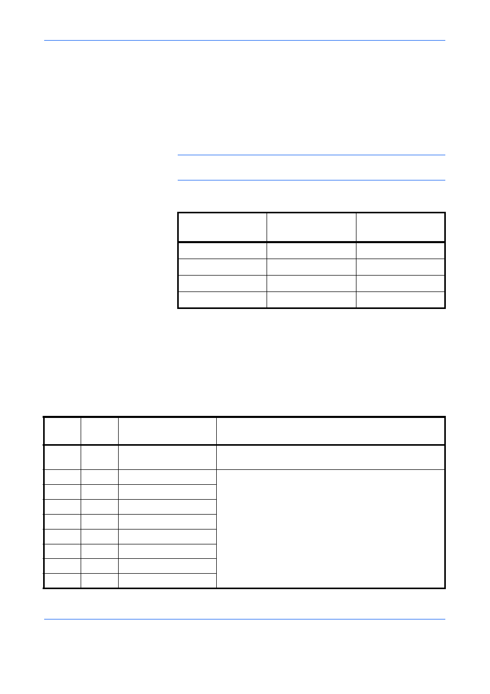
You can choose from four communication modes:
Interface Signals
Table shows the connector pins and corresponding input and output
signals of the parallel interface. Explanation of each signal is also given in
the table.
The description in [ ] indicates signal names in Auto mode and Nibble
(high) mode (IEEE 1284-compliant). In Auto and Nibble modes, these
signals are bidirectional.
Communication
Mode
Reception
Transmission
Auto (default)
High-speed/ECP
Nibble/ECP
Nibble
High-speed
Nibble
High-speed
High-speed
—
Normal
Normal
—
Pin
In or
out
Signal
Description
1
In
Strobe* [nStrobe]
A negative-going-strobe pulse causes the printer to read
and latch the data on the Data 0 [1] to Data 7 [8] signal lines.
2
In
Data 0 [Data 1]
These eight signals form one byte of data sent from host
computer to printer. Data 7 [8] is the most significant bit.
3
In
Data 1 [Data 2]
4
In
Data 2 [Data 3]
5
In
Data 3 [Data 4]
6
In
Data 4 [Data 5]
7
In
Data 5 [Data 6]
8
In
Data 6 [Data 7]
9
In
Data 7 [Data 8]