Rose Electronics Porter User Manual
Page 8
4
PORTER INSTALLATION AND OPERATIONS MANUAL
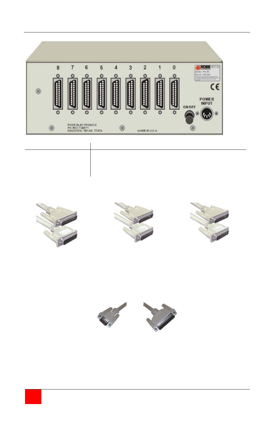
Rear panel (Serial model)
Connectors
Description
Port 0
Ports 1-8
Power input
DB25F – Connects to computer
DB25F - Connects to 8 serial devices
Din5F
Switch ON/Off
Turn unit on or off
Serial 25 pin PC to PO-8S
Rose part # CAB-PCRSx
Serial Printer to PO-8S
Rose part # CAB-PRRSx
Modem to PO-8S
Rose part # CAB-SMMx
DB-25F
2
3
7
5-6-8
-
-
-
-
DB-25M
3
2
7
20
DB-25M
2
3
7
20
-
-
-
-
DB-25M
3
2
7
6
DB-25M
2
3
6
7
20
-
-
-
-
-
DB-25M
2
3
6
7
20
Serial 9 pin PC to PO-8S
Rose part # CAB-ATRSx
DB-9F
DB-25M
2
3
5
1-6-8
-
-
-
-
2
3
7
20