Rose Electronics Porter User Manual
Page 36
32
PORTER INSTALLATION AND OPERATIONS MANUAL
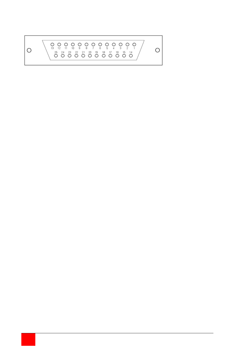
Serial Model with / 422 option
Pin
Signal Name
Direction
Description
1
Chassis Ground
Common
Connect to cable shield or equipment frame
2
TXD -
Output
Inverted transmit data out
3
RXD -
Input
Inverted receive data in
4
DTR -
Output
Inverted handshake signal; high when ready
5
DSR -
Input
Inverted handshake input; drive high when ready
7
Ground
Common
Logic ground
15
TXD +
Output
Positive transmit data out
16
RXD +
Input
Positive transmit data in
17
DTR +
Output
Positive handshake signal; low when ready
18
DSR +
Input*
Positive handshake input; drive low when ready
* = If hardware handshake is not used, connect this line to pin 7 (Ground)