Rose Electronics Porter User Manual
Page 19
PORTER INSTALLATION AND OPERATIONS MANUAL
15
If it does it indicates that possibly the unit has been subjected to a strong static discharge
or surge on its incoming power or signal lines. The other possibility is an internal chip
failure.
In addition to the data in the non-volatile ram, several other tests on the non-volatile ram
are done. If any error 4 occurs and a reset t defaults does not correct it, the unit needs
servicing. The additional errors listed below are for technical support purposes only.
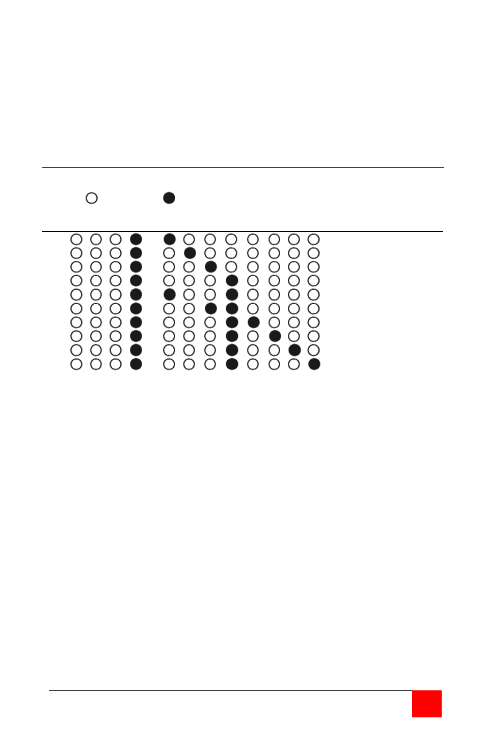
Table III LED Error Display
Legend: M=Mode LED D=Data LED B=Busy LED E=Error LED
= LED off
= LED on
M D B E
1
2
3
4
5
6 7
8
Error 1
Error 2
Error 3
Error 4
Error 41
Error 43
Error 45
Error 46
Error 47
Error 48
Error 1 . . . . . . EPROM checksum failure
Error 2 . . . . . . RAM buffer memory failure
Error 3 . . . . . . Static ram failure
Error 4 . . . . . . Non-volatile ram checksum failure
Error 41 . . . . . . Non-volatile ram in wrong box type
Error 43 . . . . . . Non-volatile ram memory failure
Error 45 . . . . . . Restore to default configuration failure
Error 46 . . . . . . A port that is not allowed is present
Error 47 . . . . . . More ports in box than listed in the non-volatile ram
Error 48 . . . . . . Wrong EPROM version
Any error not listed requires that the unit be serviced.