Models – Rose Electronics Porter User Manual
Page 7
MODELS
PORTER INSTALLATION AND OPERATIONS MANUAL
3
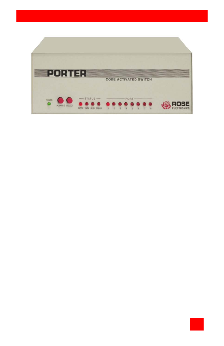
Front panel
Indicators
Description
Power
Status
Mode
Data
Busy
Error
Port
(1-8)
Green LED
On=manual / Off = normal
On=data being transferred
On = dataflow inhibited
On = data error received on serial ports
On = active port
Buttons
Advance
Select
Advance to next port
Select port
M D B
E
1
2
3
4
5
6
7
8
ο ο
ο
ο
•
ο
ο
ο
ο
ο
ο
ο
Note 1
ο ο
ο
ο
ο
ο
ο
ο
ο
ο
ο
ο
Note 2
ο ο
ο
ο
• • • • • • • •
Note 3
•
ο
ο
ο
x
x
x
x
x
x
x
x
Note 4
• • •
ο
ο
ο
ο
ο
ο
ο
ο
ο
Note 5
Note 1 ….. Unit operational, normal mode, connected to port 1
Note 2 ….. Unit operational, normal mode, null destination
Note 3 ….. Unit operational, broadcast mode, all ports selected
Note 4 ….. Unit in manual mode, displays current port connected
Note 5 ….. Unit in configuration (setup) mode