Transmitter supply voltage selection (p+, p-), Connections – Precision Digital PD6200 User Manual
Page 19
Model PD6200 Analog Input Rate/Totalizer
Instruction Manual
19
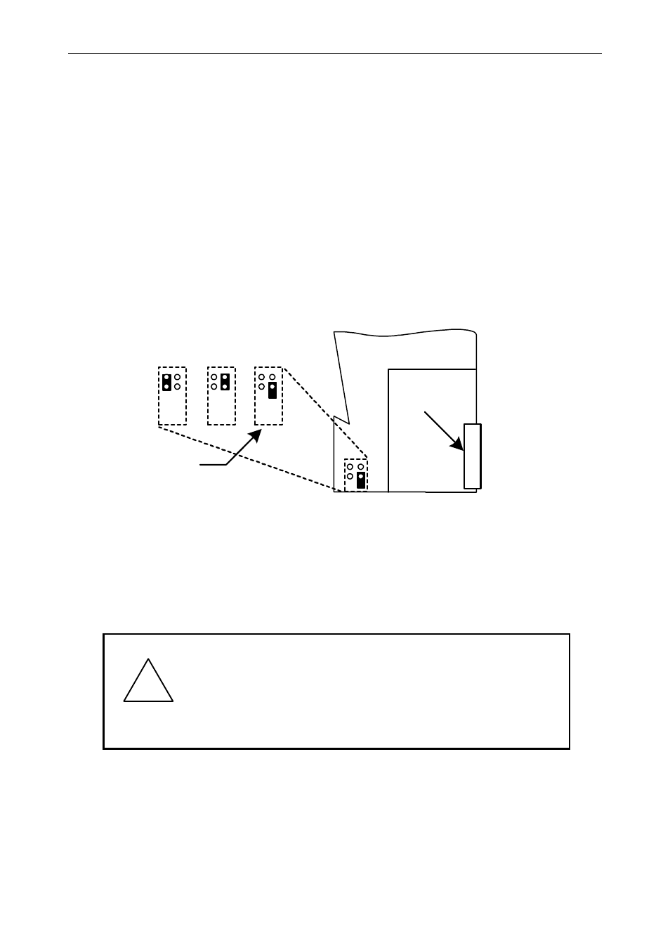
Transmitter Supply Voltage Selection (P+, P-)
All meters, including models equipped with the 12/24 VDC power
option, are shipped from the factory configured to provide 24 VDC
power for the transmitter or sensor.
If the transmitter requires 5 or 10 VDC excitation, the internal jumper
J4 must be configured accordingly.
To access the voltage selection jumper:
1. Remove all the connectors.
2. Unscrew the back cover.
3. Slide the back cover about 1 inch.
4. Configure the J4 jumper, located behind the input signal connector,
for the desired excitation voltage as shown.
MAIN BOARD
INPUT
SIGNAL
J4
5 V
10 V
24 V
J4 CONFIGURATION
Factory Default
P+
P-
mA+
COM
V+
Figure 5: Transmitter Supply Voltage Selection
Connections
All connections are made to removable screw terminal connectors
located at the rear of the meter.
!
Caution!
Use copper wire with 60°C or 60/75°C insulation
for all line voltage connections. Observe all safe-
ty regulations. Electrical wiring should be per-
formed in accordance with all applicable national,
state, and local codes to prevent damage to the
meter and ensure personnel safety.