Power supply wiring, Mtp u r series • installation, Figure 15 — power connector wiring – Extron Electronics MTP U R RS User Manual
Page 18
MTP U R Series • Installation
Power supply wiring
N
This product should be connected to a UL Listed power
supply and output rated at 12 VDC, 2A.
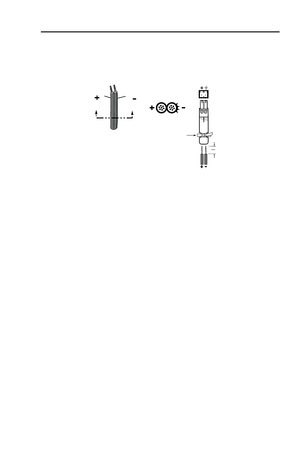
Wire the supplied male power connector (plug) as in figure 15.
Power Supply
Output
Cord
Captive
Screw
Connector
SECTION A–A
Ridges
Smooth
A
A
Tie Wrap
3"
16 (5 mm) Max.
Figure 15 — Power connector wiring
To verify the polarity before connection, plug in the power
supply with no load and check the output with a voltmeter.
C
Power supply voltage polarity is critical. Incorrect
voltage polarity can damage the power supply and
the product. If a voltmeter is not available, identify
the power cord negative lead by the ridges on the
side of the cord.
N
The length of the exposed (stripped) copper wires is
important. The ideal length is 3/16” (5 mm). Longer
bare wires can short together. Shorter wires are not
as secure in the captive screw connectors and could be
pulled out.
Do not tin the stripped power supply leads before
installing the captive screw connector. Tinned wires are
not as secure in the captive screw connectors and could
be pulled out.
W
The two power cord wires must be kept separate
while the power supply is plugged in. Remove
power before wiring.
As an alternative, an Extron P/S 123 Universal 12 VDC Power
Supply, part #60-814-01, can power multiple MTPs or other
Extron 12 VDC devices using only one AC power connector.
Insert the wired plug into the power connector on the rear panel.
15