Installation, cont’d, Mtp u r series • installation, Figure 14 — audio connector wiring – Extron Electronics MTP U R RS User Manual
Page 17
MTP U R Series • Installation
Installation, cont’d
14
e
Composite video output connector — Connect an appropriate
display device to this female BNC connector for composite
video output.
f
S-video output connector — Connect an appropriate display
device to this 4-pin mini DIN connector for S-video output.
N
Only one of the above video connectors (
c
through
f
) can be active at a time. The MTP U R device
auto detects the signal format and outputs it on the
appropriate connector. The other connectors are muted.
g
RS-232 connector —
Connect a serial communications port to
this 3.5 mm, 5-pole captive screw connector for bidirectional
RS-232 communication. Wire the connector as shown below.
Ground
Tx
Rx
Gnd
Receive
Transmit
Connected RS-232
Device Pins
MTP
Pins
Spare
Spare
Figure 13 — Pin assignments for RS-232 wiring
N
To set the connector for unidirectional communication,
see “Setting JMP1 for RS-232 communication”.
Set up the receiver for unidirectional communication
when it is to be used with an MTP DA to avoid any
RS-232/Audio detection issues.
When using with an MTPX Matrix Switcher, set up
the receiver for unidirectional for transmitter to
receiver communication; otherwise it should be set to
bidirectional when using the RS-232 output insert
connections on the matrix.
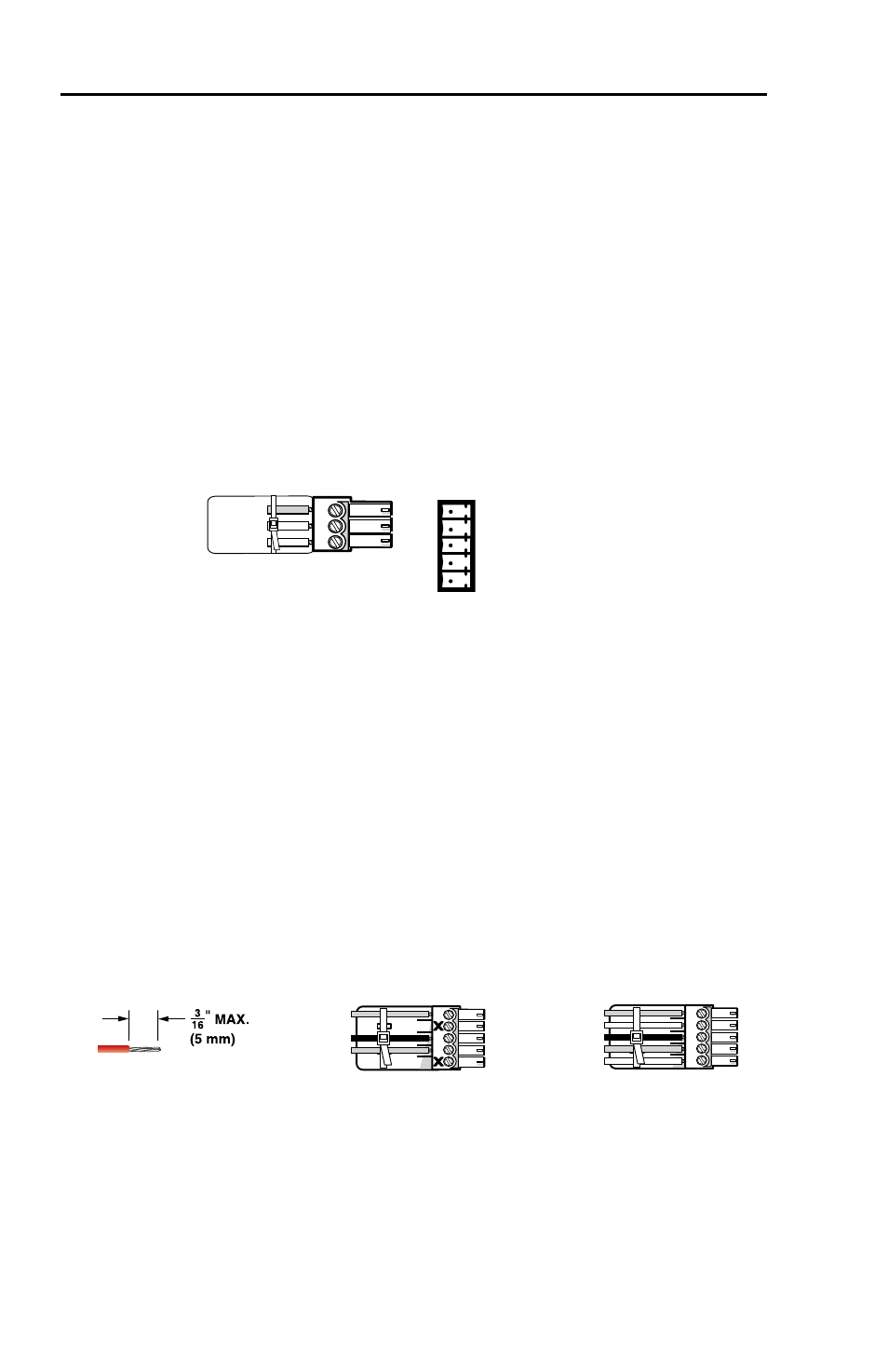
h
Audio connector (MTP U R RSA SEQ and MTP U R A models
only) —
Connect a suitable audio device to this 5-pole captive
screw connector for mono audio output.
L
MONO A
UDIO
R
L
MONO A
UDIO
R
Unbalanced Output
Balanced Output
Do not tin the wires!
Mono output 1-
Sleeve(s)
Mono output 1+
Mono output 2+
Mono output 2-
Sleeve(s)
Mono output 1
Mono output 2
NO GROUND.
NO GROUND.
Figure 14 — Audio connector wiring