Angle grinder stand, Introduction, Proper use – Powerfix Z15003 User Manual
Page 22: Description of parts and features
22 GB/MT
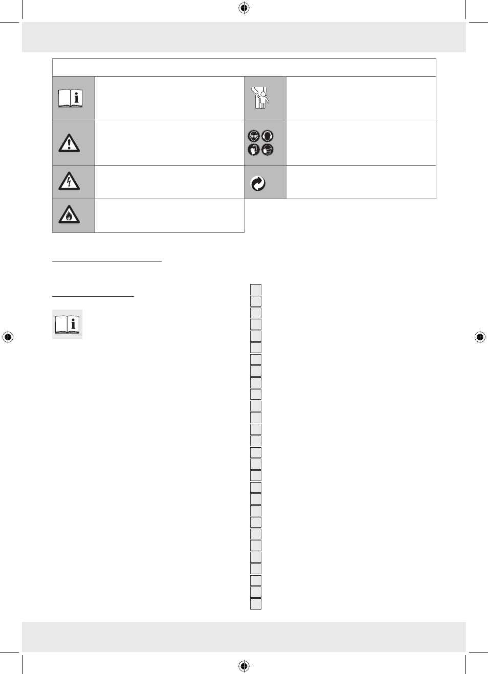
The following icons / symbols are used in this instruction manual:
Read instruction manual!
Never leave children unsupervised
with the packaging materials or the
device.
Observe caution and safety notes!
Wear protective glasses, hearing
protection, protective gloves and dust
protection mask.
Caution – electric shock!
Danger to life!
Dispose packaging and appliance in
an environmentallyfriendly way!
Risk of fire!
Angle grinder stand
Q
Introduction
Familiarise yourself with the product pri
or to assembly. Carefully read the fol
lowing assembly instructions and safety
tips. Only use the product as instructed and only
for the indicated field of application. Keep instruc
tions in a safe place. Submit all documents to a
third party if distributing the product.
Q
Proper use
This product is intended to provide a method of
holding a handheld angle grinder in a fixed position
while using it for cutting. The product is suitable for
most handheld angle grinders that take a disc 115
or 125 mm diameter disc. Any use other than that
described above or modification to the product is
not permitted and could lead to injury and/or dam
age to the product. The manufacturer accepts no li
ability for loss or damage arising from improper use.
The product is not intended for commercial use.
Q
Description of parts
and features
1
Adjustment screw with rubber buffer (short)
2
Metal rod
3
Handle
4
Nut (guard mount)
5
Safety guard
6
Plastic bushing M6
7
Plastic bushing M8
8
Washer (mounting bolt)
9
Mounting bolt M6 (angle grinder)
10
Mounting bolt M8 (angle grinder)
11
Mounting bolt M10 (angle grinder)
12
Nut (mounting bolt M6 angle grinder)
13
Nut (mounting bolt M8 angle grinder)
14
Nut (mounting bolt M10 angle grinder)
15
Distance piece (60 mm)
16
Distance piece (90 mm)
17
Distance piece (130 mm)
18
Front mounting piece
19
Plastic locating piece (mounting piece)
20
Adjustment screw with rubber buffer (long)
21
Fastening screw (vice)
22
Rotary adjustment knob (vice)
23
Vice adjustment thread (vice)
24
Guide bolt(vice)
25
Guide(vice)
26
Square nut (guide rail)
27
Stop (vice)
28
Stop (vice rear jaw)
79200_ES_IT_PT_content.indd 22
9/3/2012 1:01:57 PM