Sealey VSE5575 User Manual
Page 3
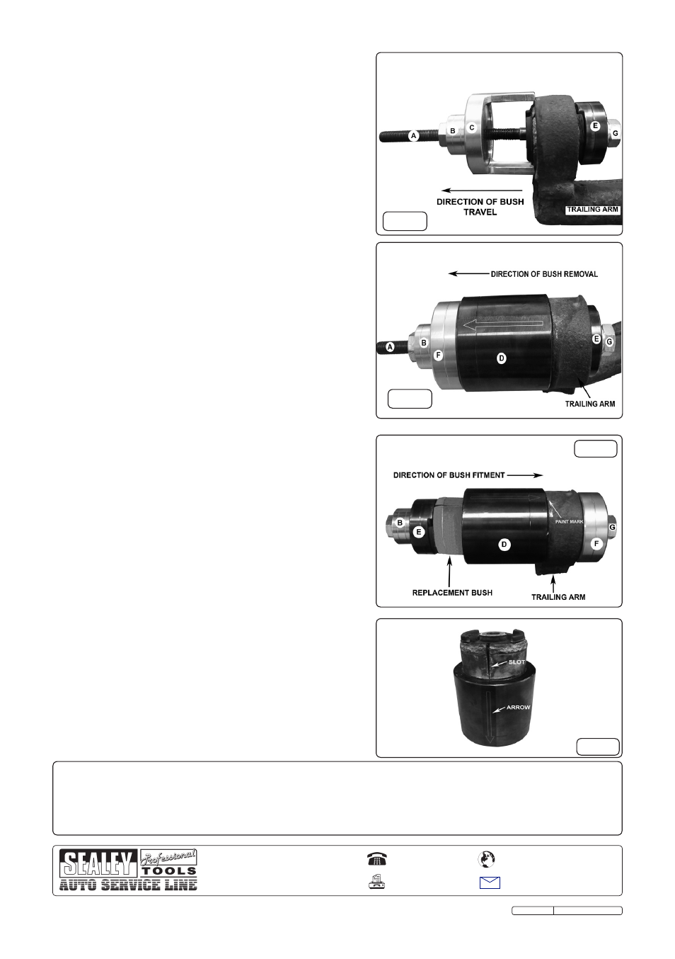
fig.5
4.5 Removal of a worn bush
To extract the worn bush correctly from the trailing arm, it
should be drawn towards the outside of the vehicle.
The original type and the slotted variant of bush will
require differing assembly configurations of the VSE5575
kit to remove them from the trailing arm, as illustrated in
the diagrams fig.5 and fig.6.
IMPORTANT: Hand tighten the Puller Nut to relieve any
slack and engage the assembly firmly over the bush. The
assembly should be aligned straight and square on the
trailing arm. Ensure the worn bush will not foul on the feet
of the Bridging Section during extraction, and the feet are
located on the trailing arm. Using suitable hand tools,
hold the Flange Nut whilst rotating the Puller Nut to
extract the worn bush.
4.6 Installation of a new bush
The slotted variant bush has superceded BMW's original
design of bush. Before installing the slotted variant bush
into the trailing arm it must first be pre-compressed. To fit
the bush correctly to the trailing arm, it must be fitted from
the outside and drawn towards the inside of the vehicle
(fig.7).
IMPORTANT: To ensure that the replacement bush does
not over compress when being installed to the trailing arm
it is essential that the Compression Sleeve is centred
over the bush aperture and aligned square and flush to
the trailing arm face.
Slide the Compression Sleeve over the bush with the
arrow facing uppermost and the arrow pointing away
from Thrust Plate.
IMPORTANT: It is essential the slot on the replacement
bush is aligned exactly beneath the arrow on the
Compression Sleeve (fig.8). The arrow acts as an
indicator for the correct positioning of the replacement
bush. Assemble the kit to the bush installation
configuration (fig.7) and ensure that the arrow on the
compression sleeve is aligned with the positioning mark
previously made on the trailing arm.
Using suitable hand tools, hold the Flange Nut whilst rotating
the Puller Nut to push the new bush through the
Compression Sleeve and into the trailing arm bush
housing.
IMPORTANT: Check the slot in the replacement bush is
correctly aligned with the paint mark made previously on
the trailing arm (fig.4).
Continue tightening the puller nut until the bush is correctly
installed and protruding equally from either side of the arm.
Removal Original Bush
Installation
Original Language Version
VSE5575 Issue:2 - 23/08/11
fig.7
fig.6
fig.8
01284 757500
01284 703534
Sole UK Distributor, Sealey Group,
Kempson Way, Suffolk Business Park
,
Bury St. Edmunds, Suffolk,
IP32 7AR
www.sealey.co.uk
Web
Removal Slotted Variant Bush
NOTE
:
It is our policy to continually improve products and as such we reserve the right to alter data, specifications and component
parts without prior notice.
IMPORTANT: No liability is accepted for incorrect use of this product.
WARRANTY: Guarantee is 12 months from purchase date, proof of which is required for any claim.
INFORMATION: For a copy of our latest catalogue and promotions call us on 01284 757525 and leave your full name and address,
including postcode.