Fig.1 – Sealey GA70 User Manual
Page 2
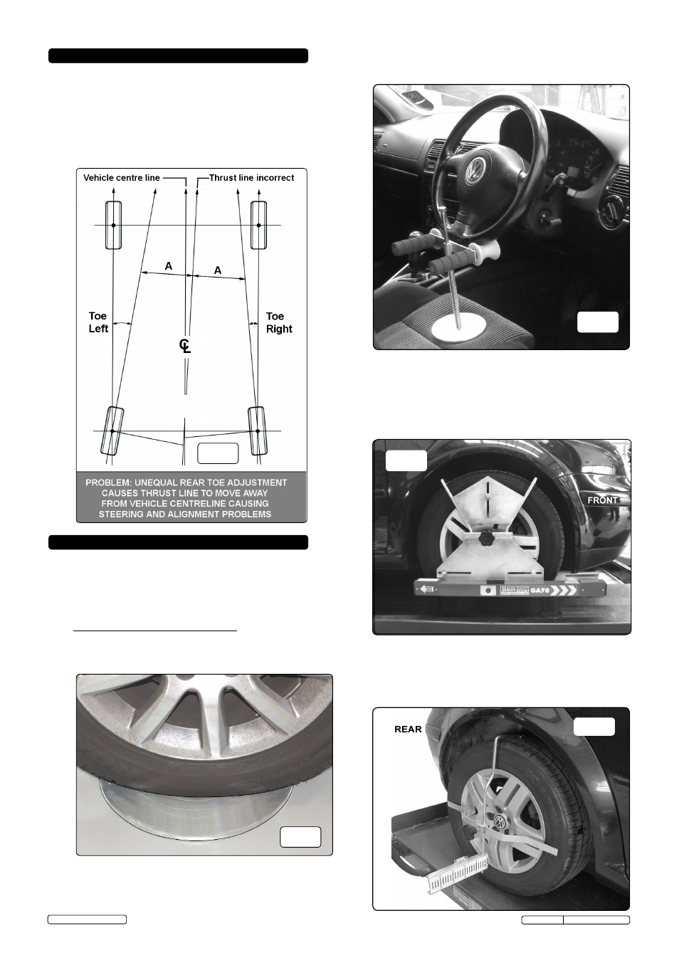
4.1. Accurate four wheel alignment should always take place with
reference to the vehicles centre line to avoid problems similar
the one shown in fig.1 where the vehicle will steer to the left
resulting in the steering wheel having to be turned to the right
to compensate. Basically, rear wheel tracking must be kept
equal to the centre line and correctly toed in or out according to
the vehicle manufactures specification in order for the vehicle
to handle correctly. check thrust lines are equal to centre line
before proceeding.
Prior to use, check that the tyre pressures are correct and if
wheel covers are fitted, remove them. Ensure that the vehicle is
on a smooth level surface with the wheels pointing straight
ahead.
Do noT reverse the vehicle into position, but drive straight
ahead into position. Ideally vehicle should be on a ramp or lift
for easier access to the track rods, if adjustment is necessary.
5.1 front to rEAr WHEEL ALIGnMEnt.
5.1.1 Place both dished turn plates in front of the front wheels, with
their curve facing downwards. Drive the vehicle onto the turn
plates, ensuring they are central to the wheels (see fig.2).
5.1.2 set steering wheel in straight ahead position and lock using the
steering wheel clamp, (see fig.3).
5. oPeraTion
4. Four wheel alignMenT
5.1.4 Hang the alignment assembly flags onto the top of the rear tyres
and make adjustments, so that the horizontal bar is sitting at
approximately the centre of the wheel and touching the tyre at
both ends. Ensure that the scale is at 90° to the wheel. check the
spirit level to ensure the correct position is achieved, (see fig.5).
fig.3
fig.2
fig.4
fig.4
fig.4
fig.5
5.1.3
Hang both laser measuring heads on the front wheels with toe
scales positioned to the front of the vehicle, (see fig.4). Note:
Extension bobbins are used for vehicles that have dished
wheels (eg 4x4 or vans) where the silver bobbins won't reach
onto the wheel rim. The Extension Bobbins fit over the silver
bobbins to give an extra 40mm of reach. note: use 13" Wheel
spacers under the Laser Measuring Heads when necessary.
Original Language Version
Original Language Version
GA70.V2 Issue: 1 - 19/02/14
© Jack sealey Limited
fig.1