Measuring castor angle & k.p.i, Checking for level floor – Sealey GA42 User Manual
Page 2
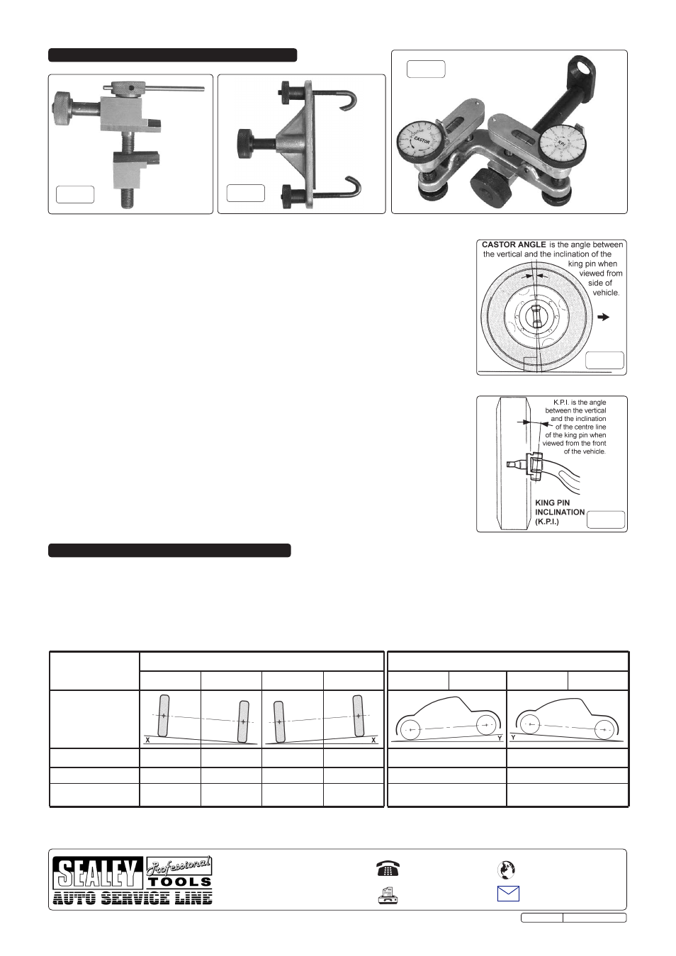
5. MEASURING CASTOR ANGLE & K.P.I.
5.1.
It is recommended that this gauge is used in conjunction with a pair of GA44 steering
turntables, to improve accuracy. The vehicle's front wheels should be positioned centrally on the
turntables as described in the instructions for the GA44. Front wheel drive vehicles should have
the foot brake applied by means of a brake pedal depressor or similar means, to prevent the
front wheels rotating, whilst using the gauge. Before taking any readings, the locking pins
should be removed from the turntables.
5.2.
There are three alternative ways of mounting the castor angle and king pin inclination gauge to
a wheel. The most common method is to use one of the wheel stud brackets as shown in fig.6.
Each wheel stud bracket is provided with a matching conical washer which may be needed to
accommodate reduced diameter studs. The centre lock bracket shown in fig.5 is for use with
centre lock wheels where the two hooks can either be attached to the spokes on the wheel or
hooked around the back of the centre lock nut. The stud axle clamp shown in fig.4 allows the
gauge to be attached to a central hub nut. When the appropriate clamp is in position, slide the
gauge onto the spindle and secure it with the knurled nut, positioning the gauge in an
approximate horizontal position. The gauge should be positioned as shown in fig.6.
5.3.
Check that the floor is level as described in Section 6, and that the tyre pressures are correct.
5.4.
Turn the front of the wheel to be checked, IN by 20° (i.e. the off-side wheel turned to the left or
the near-side wheel turned to the right.) Turn both dials on the gauge until zero is in line with
the index pointer then centre the bubbles on both spirit levels by turning the knurled screws
below each dial.
5.5.
Next turn the front of the wheel being checked, OUT by 20° (opposite to above step).
5.6.
Centre the bubbles in both spirit levels by turning the CASTOR dial and KPI dial respectively
making a note of the number of graduations through which each dial rotates.
5.7.
The scales on both dials are additive. If the king pin inclination dial is rotated a full revolution
and the spirit level bubble is still not centred continue to turn the dial until it is centred. The king
pin inclination angle is therefore the sum of the total number of graduations that the dial has
been turned through. The same applies to the castor angle dial readings.
5.8.
If the floor is not level, make any necessary adjustments to the readings (See Section 6 chart).
5.9.
Any changes deemed necessary as a result of using this set, must be made strictly in accordance
with the vehicle manufacturer’s recommendations.
6.1.
Check that the floor is level using the camber angle gauge as follows. Turn the dial marked degrees (see fig.2.A) so that ‘0’ is in line
with the index pointer. Place the gauge on the floor at right angles to the wheel to be checked (place parallel to the wheel when
measuring castor angle). If the bubble in the spirit level is not centred, then the floor is not level. Turn the dial in the required direction until
the bubble is centred. The slope of the floor in degrees is represented by the number of graduations turned on the dial.
6.2.
Adjusting readings when the floor is sloping. Readings can still be taken on a sloping surface up to a maximum of 3°. Establish the
angle of the slope using the camber gauge as described above. Note the direction of the slope and the vehicles orientation on it. To
make a correction, the slope angle should either be added to, or subtracted from the reading according to the chart below. Where the
chart indicates N/A this means that no adjustment is necessary in that particular orientation.
SLOPING FLOOR
SLOPING SIDE TO SIDE
SLOPING LENGTH WISE
COMPENSATION
CHART
NEARSIDE (HIGH)
OFFSIDE
NEARSIDE
OFFSIDE (HIGH)
REAR
FRONT (HIGH) REAR (HIGH)
FRONT
SLOPE ANGLE
ORIENTATION
CAMBER ANGLE
ADD X°
SUBTRACT X° SUBTRACT X° ADD X°
N/A
N/A
KING PIN INCLINATION SUBTRACT X° ADD X°
ADD X°
SUBTRACT X°
N/A
N/A
Subtract Y° from + readings
Add Y° to + readings
CASTOR ANGLE
N/A
N/A
N/A
N/A
Add Y° to - readings
Subtract Y° from - readings
6. CHECKING FOR LEVEL FLOOR
NOTE: It is our policy to continually improve products and as such we reserve the right to alter data, specifications and component parts without prior notice.
IMPORTANT: No liability is accepted for incorrect use of this product.
WARRANTY: Guarantee is 12 months from purchase date, proof of which will be required for any claim.
INFORMATION: For a copy of our latest catalogue and promotions call us on 01284 757525 and leave your full name and address, including postcode.
Sole UK Distributor, Sealey Group,
Kempson Way, Suffolk Business Park,
Bury St. Edmunds, Suffolk,
IP32 7AR
01284 757500
01284 703534
www.sealey.co.uk
Web
fig.6
fig.5
fig.7
fig.8
fig.4
Original Language Version
GA42.V2 Issue: 1 - 29/07/10