Instructions – Sealey SX0408 User Manual
Page 2
4. inSTRucTionS
NOTE: It is our policy to continually improve products and as such we reserve the right to alter data, specifications and component parts without prior notice.
iMPoRTAnT: No liability is accepted for incorrect use of this product.
WARRAnTY: Guarantee is 12 months from purchase date, proof of which will be required for any claim.
inFoRMATion: For a copy of our latest catalogue and promotions call us on 01284 757525 and leave your full name and address, including postcode.
Numbers in brackets refer to Fig.1
noTE: To minimise the possibility of damage to the engine, it is advisable to remove the cylinder head from the engine to work on it. Alternatively,
remove the relevant injector and connect an air line via an appropriate adaptor to the aperture to ensure dirt and swarf do not enter the
combustion chamber as the procedure is carried out.
Wear eye protection.
4.1.
Push fit Star Socket (6) onto the top of the glow plug; it may need to be tapped on lightly. Then, using a ⅜” ratchet, remove/break off the
top part of the glow plug.
4.2.
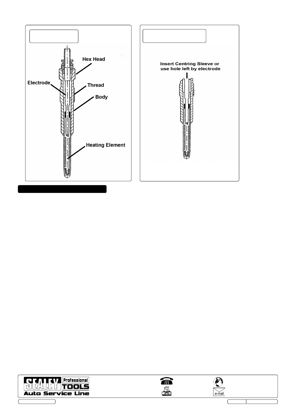
(See Fig.3) Insert Centring Sleeve (4) into the recess in the top of the glow plug. Fit Pilot Drill (10) to an electric drill and insert pilot drill
into centering sleeve, drill a pilot hole in the centre of the glow plug remains. Ensure that pilot drilling is at least 15mm deep. Clean away
the swarf using an air line.
note: If the electrode can be withdrawn in one piece, the aperture created may be used as a pilot.
If this is the case, proceed to 4.4.
4.3.
Fit either 7mm (7) or 9mm (8) Drill Bit into the Drill Holding Adaptor (2) and lock in place with the grub screw, using the hex key (5).
Make sure that the grub screw bears on the flat, machined into the shank of the drill bit. Carefully drill out the centre of the glow plug and
threaded portion of glow plug body. Take care not to damage the female threads in the cylinder head.
Clean out the swarf using an air line.
4.4
Fit the ¼” tap provided into the ratchet T-bar. Cut a thread with this in the remains of the glow plug body, cutting at least
15mm of thread.
4.5.
Screw a Puller Adaptor Mandrel (3) into the thread that has just been cut into the glow plug. Remove the nut from the force screw in the
Puller Housing (1) and thread the force screw onto the mandrel. Slide the outer sleeve of the puller housing over the force screw.
4.6.
Re-fit the nut to the force screw with the collar facing the outer sleeve. Hold the head of the force screw with a 12mm wrench or socket
and wind the nut down using a 30mm wrench.This will draw the remaining lower part of the glow plug free from the cylinder head.
4.7.
Fit either M8 (12) or M10 (11) Tap into Ratchet T-Bar (9). Run the tap down to clean/restore the threads in the cylinder head.
An application of grease to the tap will both lubricate and help contain the swarf.
4.8.
Clean thoroughly the thread and surrounding area and make sure that the combustion chamber (if head is in-situ) is free from debris
before fitting a replacement glow plug.
4.9.
Ensure all tools are removed from the engine bay and returned to the tool tray, and store this in a safe, dry, childproof location.
01284 757500
www.sealey.co.uk
01284 703534
Web
Sole uK Distributor, Sealey Group,
Kempson Way, Suffolk Business Park,
Bury St. Edmunds, Suffolk
IP32 7AR
SX0408.V2 Issue No: 1 - 10/09/13
Original Language Version
© Jack Sealey Ltd
Fig.2-Glow Plug
construction
Fig.3-Glow Plug with
Electrode withdrawn