Fig.2, Fig.3, Fig.1 fig.4 – Sealey VS905 User Manual
Page 2
4.1.
Measurement Operation
4.1.1. Hold the thermometer by the handle grip and point it towards the surface to be measured. The meter will compensate
automatically for temperature deviations from the ambient temperature.
4.1.2. Pull and hold the trigger to turn the thermometer on and begin testing.
4.1.3. Release the trigger and the ‘hold’ display icon will appear on the LCD indicating that the reading is held.
4.1.4. The thermometer will automatically power down seven seconds after the trigger has been released.
4.2.
Measurement Considerations
4.2.1. Make sure the target is larger than the thermometer’s spot size. The smaller the target, the closer you should be to it.
4.2.2. When accuracy is critical, make sure the target is at least twice the size of the spot.
4.3.
Locating Hot Spots
4.3.1. To find a hot spot, aim the thermometer outside the area of interest, then scan across with an up and down motion until you
locate the hot spot indicated by the highest reading on the LCD display.
NOTES! - Not recommended for use in measuring shiny or polished metal surfaces (stainless steel, aluminium etc.) see Emissivity
chart below.
- The unit cannot measure through transparent surfaces such as glass. It will measure the surface temperature of the glass
instead.
- Steam, dust, smoke etc. can prevent accurate measurement by obstructing the lase beam.
fig.2
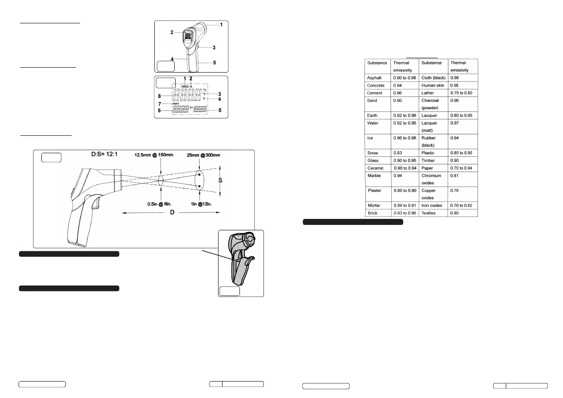
GENERAL DESCRIPTION (fig.1)
1
Infrared sensor
2
LCD Display
3
Measurement trigger
4
Handle grip
5
Battery cover
DISPLAY DESCRIPTION (fig.2
1
Data hold
2
Laser ‘ON’ symbol
3
°C/°F symbol
4
Low power symbol
5
Emissivity symbol and value
6
MAX temperature value recorded while trigger held
7
MAX symbol
8
Current temperature value
fig.3
Distance & spot size (fig.3)
As the distance (D) from the object increases, the diameter (S) of the area measured by the unit becomes larger.
To switch between °C and °F pull forward the battery cover and slide the switch indicated in fig.4.
3. SET UP
° C to °F switch
5.
TYPICAL APPLICATIONS
4. OPERATION
WARNING! When working on vehicle systems, take all the precautions necessary to ensure the safety of yourself and others
- always refer to vehicle manufacturer’s handbook/service manual. The purpose of this tool dictates that it will be used close
to very hot equipment and therefore extreme care should be exercised.
5.1.
Air Conditioning
With the air conditioning set to maximum cooling, the temperature of the output air should be at least 15°C colder than the
outside ambient once the system has stabilised. Do not place the thermometer directly in the cold air stream (thermal shock)
but rather hold it to one side and take the temperature of the air duct. If the air temperature differential is less than 15°C
have the A/C system checked.
5.2.
Heater
With the engine running, and at normal operating temperature, A/C ‘off’ and heater controls ‘on’ measure the temperatures of
the heater inlet and outlet hoses/pipes at the engine compartment bulkhead. The outlet hose/pipe should be approximately
10°C cooler than the inlet. If the differential is significantly more than this the flow through the heater core is restricted and
the system should be investigated.
5.3.
Radiator
When the engine is running at normal operating temperature, there should be an even temperature drop between the
radiator inlet and outlet. Check the whole radiator surface for any ‘cold’ spots which would indicate a blockage.
5.4. Thermostat
Under normal operation the thermostat will will open as the engine reaches operating temperature, releasing hot coolant into
the hose linking the thermostat housing to the radiator.
Use the thermometer to monitor the hose temperature, adjacent to the thermostat housing, as the engine warms up to
operating temperature (85-105°C).
1) If the hose temperature abruptly and quickly increases the thermostat is functioning correctly.
2) If the temperature increases gradually and does not reach operating level the thermostat has failed in the open condition
(or is missing).
3) If the temperature does not rise at all the thermostat has failed in the closed position or coolant is not flowing for some
other reason (air lock, pump failure etc.) and further investigation is required.
4) A fluctuating temperature indicates a weak thermostat spring or air in the system.
Emissivity Chart
fig.1
fig.4
Original Language Version
© Jack Sealey Limited
VS905 Issue:2(L) - 04/08/14
Original Language Version
© Jack Sealey Limited
VS905 Issue:2(L) - 04/08/14
4.4. Emissivity
4.4.1. Emissivity is a term used for the ability of a surface to radiate energy. Most (90% of typical applications) organic materials and
painted or oxidised surfaces have an emissivity of 0.95 (pre-set in the thermometer).
4.4.2. Inaccurate readings will result from measuring shiny or polished surfaces. To compensate, cover the surface to be measured
with masking tape or flat black paint.
4.4.3. Allow time for the tape to reach the same temperature as the material underneath it. Measure the temperature of the tape or
painted surface.