Operation – Sealey DBG5010 User Manual
Page 2
5. OPERATION
5.1. Setting up (The dial ball gauge is a comparator not a measuring tool)
5.1.1. Measure the bore diameter or gap to be measured to the nearest millimetre with a rule or vernier callipers. The bore or gap
must range between 50mm and 160mm nominally with this tool. (up to 164.5 with spacers)
5.1.2. select the range of parts required, anvils, spacers and 50mm distance piece using the table on the last page.
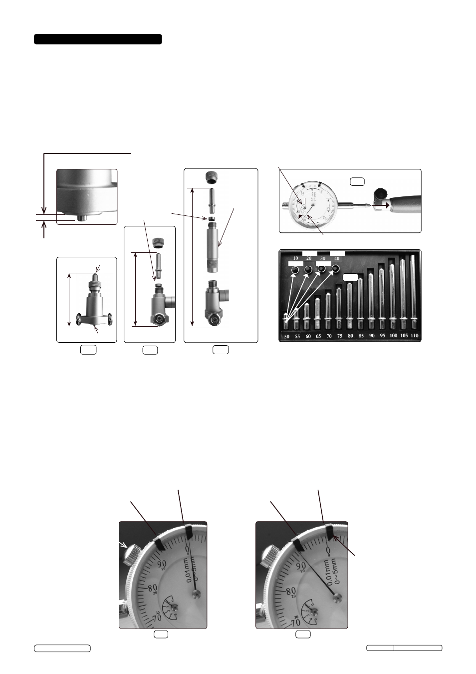
5.1.3. Assemble the dial bore gauge with selected parts as shown in fig.1, fig.2 and fig.3. Ensure all components are clean and when
assembled are finger and thumb tight; no tools are to be used.
5.1.4. Insert the dial stylus into the probe body as shown in fig.4. The stylus will meet with resistance internally and the dial pointer will
begin to rotate clockwise. one complete cycle of the pointer is recommended for registration and will be indicated by the secondary dial
indicator annotated 1-5. The small pointer should now be indicating "1" [one].
5.1.5. Clamp the dial stem with the thumb screw.
DO NOT overtighten.
5.2. Calibration
5.2.1. depending upon accuracy requirement, calibration can be achieved with slip gauges, micrometer or vernier callipers. In our instructions
example the micrometer is suggested, which has similar accuracy to the dial gauge.
5.2.2. set the micrometer (50mm-75mm) to the target size "x", for example Ø63.50 and lock. In our example the tolerance required is H9 from
Bs 4500:1969 (+.074/-0).
5.2.3. From instruction 5.1.2 and the tables on the back page; parts required are the anvil 60 plus spacer ring 30 or 40, from item 5 in fig.1.
Assemble as shown above.
5.2.4. Maneouvre the gauge anvil and nib inside the measuring gap of the micrometer (fig.11). This activity could be eased by assistance or
carefully clamping the micrometer with toolmakers clamps on to an angle plate.
5.2.5. observe the large dial pointer movement. It is essential that the axis of the gauge anvil and spring loaded nib are centralised in the
micrometer measuring faces. It is essential to observe the total sweep of the dial pointer using the small dial. remember from the initial
setting the pointer had rotated one full cycle.
5.2.6. When satisfied with alignment, hold the position and rotate the dial bezel until the "0" [zero] aligns with the pointer. lock the bezel with
the thumb screw. Your dial bore gauge has now been calibrated for use in a Ø63.00 to Ø64.00 bore ie +/-0.5mm of target.
5.2.7. The tolerance band can now be set using the two "markers" on the bezel. our example states the tolerance band to be +0.074 to -0. set
one marker opposite and in line with "0" [zero] (fig.6) and the other +7.4 (fig.7) divisions apart. note! the larger the deflection the smaller
the bore.
nib
Anvil
Without spacer
(1mm)
(2mm)
(3mm)
(4mm)
use the spacer rings to achieve "x" = 51,52,53,54,56 etc..
spacer ring for
intermediate sizes
distance
piece
(50mm)
Insert the stylus for 1 full large pointer revolution
fig.5
fig.4
fig.3
fig.2
fig.1
small pointer on "1"
Pass
Pass
Fail
Fail
Fail
Fail
Tolerance markers
fig.6
fig.7
Example for reference only
Bezel clamping screw.
Please note the
tolerance markers will
not pass the screw when
clamped.
dBG5010 Issue: 1 - 08/04/14
Original Language Version
© Jack sealey limited
Be aware, nib projection is 2mm.
Aim for 0.5mm to 1.5mm as the
measurement zone.
With spacer
With spacer and distance piece