Fig.4, Instructions – Sealey VS311 User Manual
Page 2
4. InSTRUcTIOnS
VS311.V2 Issue No: 1 - 04/11/13
NOTE: It is our policy to continually improve products and as such we reserve the right to alter data, specifications and component parts without prior notice.
IMPORTAnT: No liability is accepted for incorrect use of this product.
WARRAnTY: Guarantee is 12 months from purchase date, proof of which will be required for any claim.
InFORMATIOn: For a copy of our latest catalogue and promotions call us on 01284 757525 and leave your full name and address, including postcode.
nOTE: To minimise the possibility of damage to the engine, it is
advisable to remove the cylinder head from the engine prior to
commencing work of this nature. The tap guide system
included with this set will significantly reduce the ingress of
swarf/debris into the combustion chamber and cylinder.
Always wear eye and hand protection when cleaning any
swarf/debris from the engine. A full range of personal safety
equipment is available from your Sealey Dealer.
4.1. Repairing a damaged thread using a tap
WARnInG! Ensure you have read, understood and apply
Section 1 safety instructions.
4.1.1. Determine the size of the thread to be repaired. This can be
done by carefully using the insert drivers to compare with the
thread of an undamaged glow plug aperture.
4.1.2. Using the correct size of tap and insert guide, assemble the
set as shown in fig.2 and fig.3.
4.1.3. If a ring spanner is to be used, position on the tap before
inserting the insert guide pin into the glow plug aperture. Apply
a layer of general purpose grease to the insert guide to help
prevent swarf/debris from entering the engine and place into
the glow plug aperture.
4.1.4. Hold the knurled head (17) and position the guide rod (16)
so that the insert guide pin is squarely positioned in the glow
plug aperture.
4.1.5. Using a spanner with adequate downward pressure, carefully
run the tap down the damaged thread 1/2 of a turn forward
then 1/4 of a turn back to repair the damaged thread. Always
use a suitable cutting fluid. Periodically remove the tap and
insert guide to clean away the swarf/debris. Apply a layer
of general purpose grease to the insert guide before
re-inserting into the glow plug aperture. Continue until the full
length of the thread has been repaired.
nOTE: It is very important to clean away as much swarf/debris
as possible during the thread cutting process to avoid any
ingress into the engine.
4.1.6. Once the thread has been repaired, ensure that all swarf/
debris has been completely removed and carefully fit the
glow plug.
4.1.7. Ensure all tools are removed from the engine bay and stored
away. Store in a safe, dry, childproof location.
01284 757500
www.sealey.co.uk
01284 703534
Web
Sole UK Distributor, Sealey Group,
Kempson Way, Suffolk Business Park,
Bury St. Edmunds, Suffolk
IP32 7AR
Original Language Version
Insert/Tap/Guide Configurations (Refer to fig.1 & fig.2)
Insert Size:
Tap Size:
Guide Size:
M8x1.0 (1)
M10x1.0 (6)
M8 (13)
M10x1.0 (2)
M12x1.0 (8)
M10 (14)
M10x1.25 (3)
M12x1.25 (9)
M10 (14)
M12x1.25 (4)
M14x1.25 (10)
M12 (15)
4.2. Repairing a damaged thread using an insert
WARnInG! Ensure you have read, understood and apply
Section 1 safety instructions.
4.2.1. Determine the size of the thread to be repaired. This can be
done by carefully using the insert drives to compare with the
thread of an undamaged glow plug aperture.
4.2.2. Using the table above, assemble the set, as shown in fig.2 and
fig.3 with the correct tap and insert guide configuration for the
size of insert required.
4.2.3. If a ring spanner is to be used, position on the tap before
inserting the insert guide into the glow plug aperture. Apply
a layer of general purpose grease to the insert guide to help
prevent swarf/debris from entering the engine and place into
the glow plug aperture.
4.2.4. Hold the knurled handle and position the guide rod so that the
insert guide is squarely positioned in the glow plug aperture.
4.2.5. Using a spanner with adequate downward pressure, carefully
run the tap down through glow plug aperture 1/2 of a turn
forward then 1/4 of a turn back to cut a thread for the insert.
Always use a suitable cutting fluid. Periodically remove
the tap and insert guide to clean away the swarf and debris.
Apply a layer of general purpose grease to the insert guide
to assist with the removal of swarf/debris before re-inserting
into the glow plug aperture. Continue until the length of thread
cut is sufficient to accommodate the insert. Ensure that all
swarf/debris is completely removed from the glow plug
aperture.
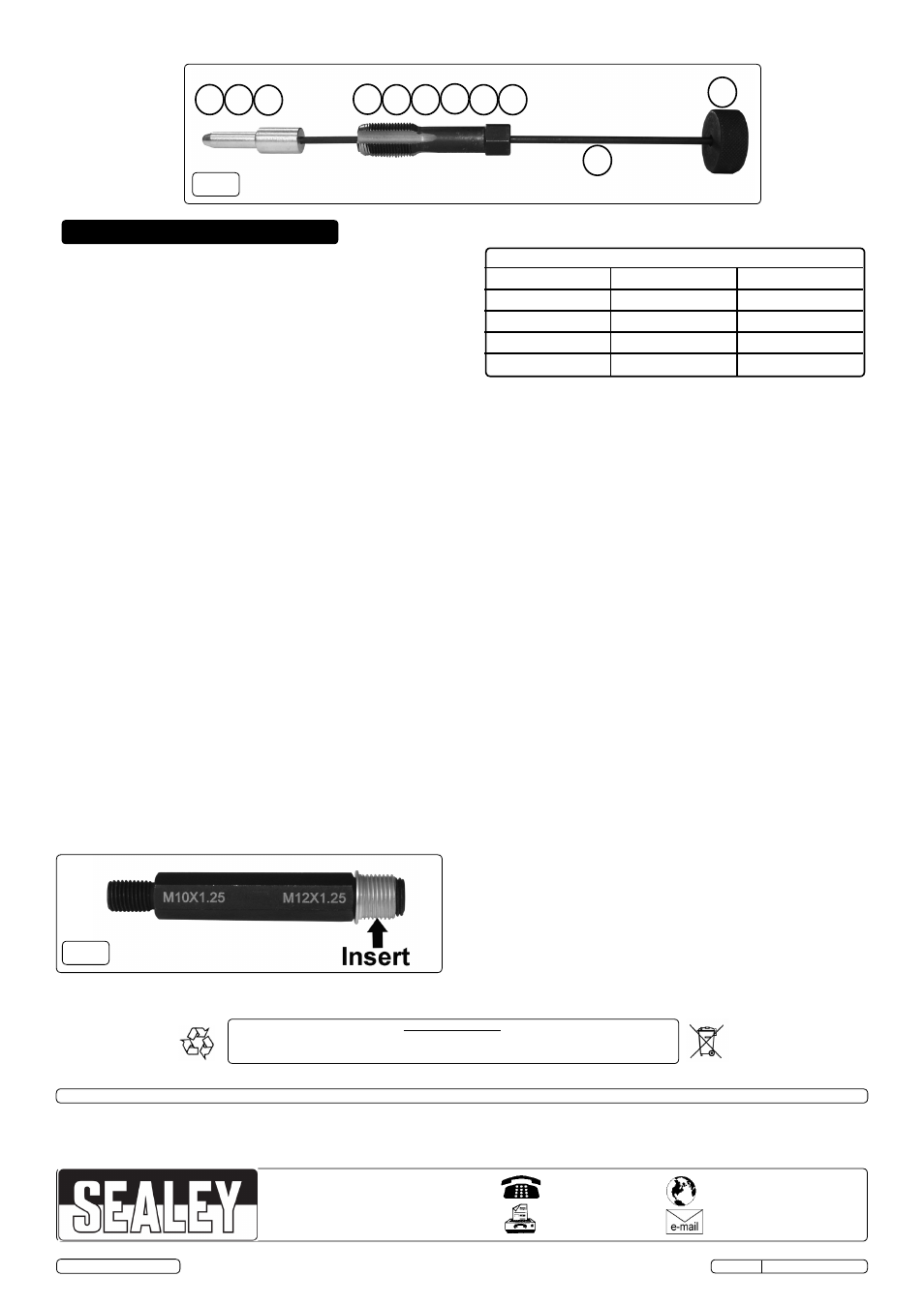
4.2.6. Screw the insert onto the relevant insert drive (fig.4).
4.2.7. Apply a suitable thread locking solution to the exterior thread
of the insert. Screw the insert into the prepared glow plug
aperture until the flange at the top of the insert locates at the
top of the aperture thread and tighten using a suitable
spanner.
4.2.8. Remove the insert driver, taking care not to dislodge the insert.
4.2.9. Allow the thread locking solution to completely cure before
fitting the glow plug.
4.2.10. Ensure all tools are removed from the engine bay and stored
away. Store in a safe, dry, childproof location.
fig.4
Parts support is available for this product. Please log on to www.sealey.co.uk, email [email protected] or phone 01284 757500
© Jack Sealey Limited
fig.3
13 14 15
16
17
10
5 6 7 8 9
Environmental Protection.
Recycle unwanted materials instead of disposing of them as waste. All tools, accessories and packaging should be sorted, taken
to a recycle centre and disposed of in a manner which is compatible with the environment. When the product is no longer
required' it must be diposed of in an environmentally protective way