Fig.1 fig.2 fig.3, Content & assembly 4. operation 5. maintenance – Sealey EFS/93 User Manual
Page 2
Original Language Version
efs93.V4 Issue no.1 23/03/10
WARNING! Before operating the extractor ensure that you
read, understand and apply the safety instructions in
Section 1.
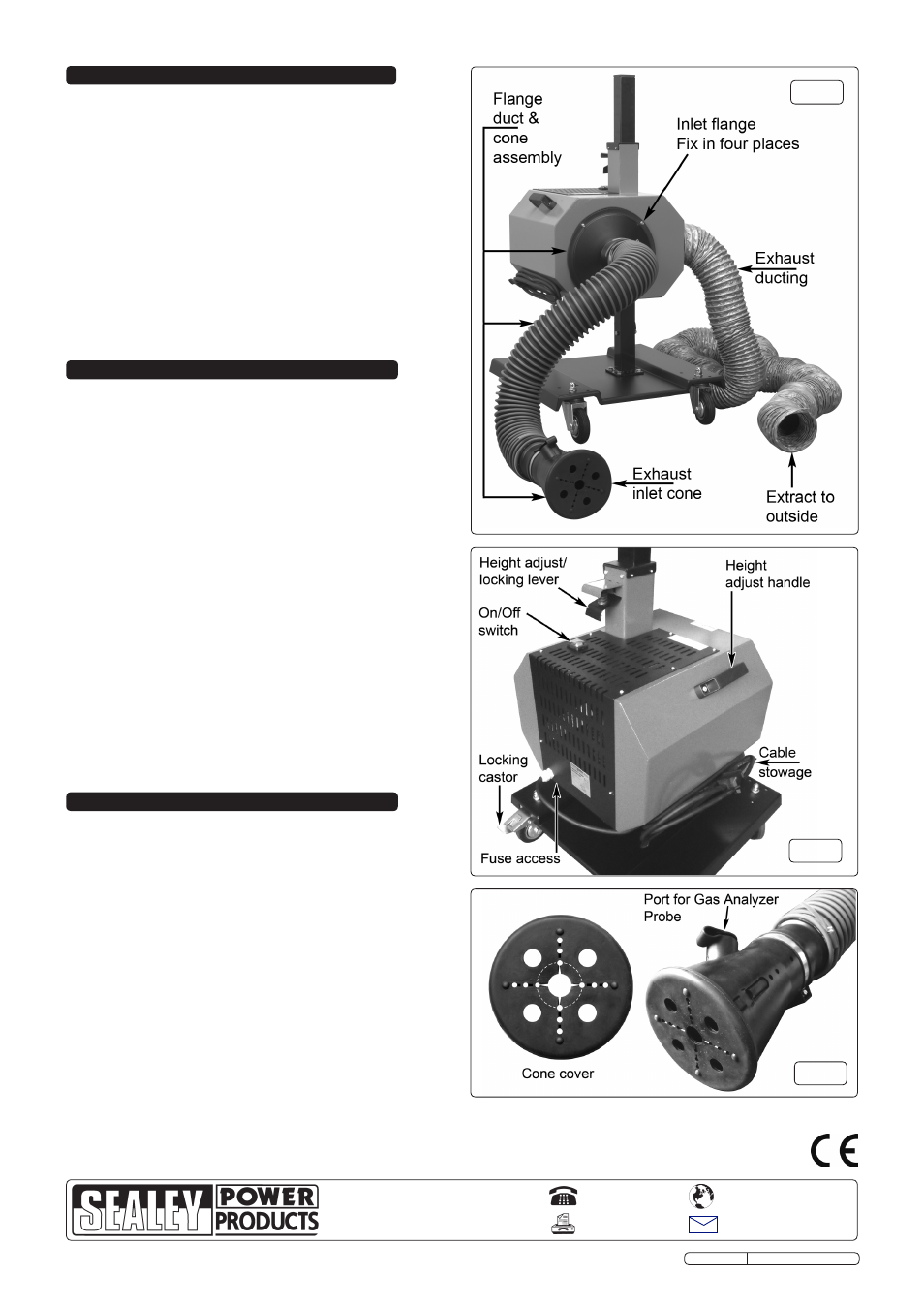
4.1. Move the unit into a suitable position at the rear of the vehicle
and stop it moving by pressing the foot levers on both locking
castors. see fig.2.
4.2. Adjust the extractor height as necessary using two hands. first
take hold of the fixed handle on the main body. Place the other
hand under the locking lever and lift it to release the
mechanism. using both hands move the unit up or down
the column as required. release the locking lever to lock the
unit at the required height on the column.
4.3. Push the exhaust cone onto the vehicle exhaust pipe. the
exhaust cone cover has a series of slots and holes across
each axis. depending on the size of the exhaust pipe it may be
necessary to carefully slit the face of the cover with a sharp
knife equally along each axis to get the cover to fit. see fig.3.
Alternatively, if the exhaust outlet is suitable, the cover can be
completely removed.
4.4. uncoil the mains cable and plug it into the mains supply. turn
on the extractor using the on/off switch on top of the main
body. see fig.3.2.
4.5. there is a port on the side of the cone (see fig.3) which allows
the connection of a gas analyser probe if required.
Note: take care to ensure that there is no possibility of paper, plastic
or other foreign bodies being sucked into the extractor cone.
3. CONTENT & ASSEMBLY
4. OPERATION
5. MAINTENANCE
3.1. unpack the equipment and check against the list below for
missing or damaged items. (see also fig.1) In the event of a
fault contact the supplier.
1. extractor unit and stand assembly.
2. extractor cone, duct & flange inlet assembly.
3. exhaust ducting (6mtr.)
5. 4 screws and washers (loosely fitted in housing)
3.2. remove the four socket cap screws and washers from around
the inlet aperture on the main housing. Align the four holes on
the inlet flange with the holes around the aperture and fix in
place with the four socket cap screws and washers.
3.3. fit exhaust ducting to the port on the side of the unit and
retain it with a suitable jubilee clip/strap.
3.4. route the exhaust ducting to outside the building, keeping the
ducting as straight and level as is practical. note that the
ducting is relatively easily damaged and should be routed, as
far as possible, away from walkways etc.
WARNING! Disconnect the unit from the mains power
before servicing or performing any maintenance.
5.1. to replace the fuses firstly undo the eight self tapping screws
that hold the black ventilation cover in place on the top and rear
of the unit. the cover has wiring attached to it and must be
properly supported whilst fuses are being changed. the
cartridge fuse holder is mounted at an angle on the left, inside
the cabinet. replace a blown fuse with one of an identical size,
shape and specification.
5.2. refit the ventilation cover.
NOTE: It is our policy to continually improve products and as such we reserve the right to alter data, specifications and component parts without prior notice.
IMPORTANT: no liability is accepted for incorrect use of this product.
WARRANTY: Guarantee is 12 months from purchase date, proof of which will be required for any claim.
INFORMATION: for a copy of our latest catalogue and promotions call us on 01284 757525 and leave your full name and address, including postcode.
01284 757500
01284 703534
Sole UK Distributor, Sealey Group,
Kempson Way, suffolk Business Park
,
Bury st. edmunds, suffolk,
IP32 7Ar
www.sealey.co.uk
Web
fig.1
fig.2
fig.3